Difference between revisions of "Tarkin"
| (10 intermediate revisions by 3 users not shown) | |||
| Line 1: | Line 1: | ||
| − | Tarkin is the new large-format laser cutter in the space. It's a hot-rod custom-built laser cutter based on an RF CO2 10.6um laser and the latest in C-rail linear rails and a closed-loop servo-stepper motion system with a Ruida RDC6445G controller running Lightburn software. It features 225W of power on a 1.6M x 1.0 M (63"x39") cutting bed, powered Z, 16MP alignment camera, and air assist. | + | Tarkin is the new large-format laser cutter in the space, currently the most capable [[:Category:Lasers|of our lasers]] for 2-d operations. It's a hot-rod custom-built laser cutter based on an RF CO2 10.6um laser and the latest in C-rail linear rails and a closed-loop servo-stepper motion system with a Ruida RDC6445G controller running Lightburn software. It features 225W of power on a 1.6M x 1.0 M (63"x39") cutting bed, powered Z, 16MP alignment camera, and air assist. |
It's quite large and capable -- we don't think there's anything like it in central Texas. | It's quite large and capable -- we don't think there's anything like it in central Texas. | ||
| Line 48: | Line 48: | ||
=== ''Workspace'' === | === ''Workspace'' === | ||
| − | Lightburn's work area on the PC. This is the same as the machine bed only if you make the workspace size the same as machine bed size and operate in absolute coordinates. Otherwise, where your job is placed on the workspace is not necessarily where the job will be when you go to the machine bed, and your workspace can be declared in a different size than the machine bed. Note that in either case, your job (the actual content) will probably be smaller than the whole declared workspace, and cannot be located outside the workspace when you actually want to send it to the laser. | + | Lightburn's work area on the PC. This is the same as the machine bed only if you make the workspace size the same as machine bed size and operate in absolute coordinates. Otherwise, where your job is placed on the workspace is not necessarily where the job will be when you go to the machine bed, and your workspace can be declared in a different size than the machine bed. Note that in either case, your job (the actual content) will probably be smaller than the whole declared workspace, and cannot be located outside the workspace when you actually want to send it to the laser. Raster content cannot use the entire width of the workspace as it requires enough extend space on either side to decelerate and accelerate back. You will not know if it has enough extend space until trying to run the job at the machine. |
=== ''Job'' === | === ''Job'' === | ||
| Line 324: | Line 324: | ||
==== NO PVC ==== | ==== NO PVC ==== | ||
NO PVC or ANY FORM OF "VINYL", INCLUDING TRADITIONAL VINYL RECORDS. This is 60% chlorine atoms by weight, and the fumes are corrosive to the equipment. Do not attempt! | NO PVC or ANY FORM OF "VINYL", INCLUDING TRADITIONAL VINYL RECORDS. This is 60% chlorine atoms by weight, and the fumes are corrosive to the equipment. Do not attempt! | ||
| + | |||
| + | ==== NO PTFE (Teflon) ==== | ||
| + | Produces toxic and corrosive gases | ||
==== NO Polycarbonate ==== | ==== NO Polycarbonate ==== | ||
NO POLYCARBONATE ("LEXAN"). This includes CDs, DVDs, and BluRay disks. Although it looks very much like acrylic, polycarbonate does not cut. It turns brown and cracks and produces a ton of soot chains that dirty the optics and whole machine in seconds. | NO POLYCARBONATE ("LEXAN"). This includes CDs, DVDs, and BluRay disks. Although it looks very much like acrylic, polycarbonate does not cut. It turns brown and cracks and produces a ton of soot chains that dirty the optics and whole machine in seconds. | ||
| − | |||
| − | |||
| − | |||
==== NO METAL ==== | ==== NO METAL ==== | ||
| Line 338: | Line 338: | ||
=== Copper Wire Flame Test === | === Copper Wire Flame Test === | ||
| − | When in doubt, there is a copper wire "flame test": | + | When in doubt, there is a copper wire "flame test" specifically for the presence of toxic/corrosive chlorine as found in PVC: |
https://www.youtube.com/results?search_query=laser+cutter+flame+test | https://www.youtube.com/results?search_query=laser+cutter+flame+test | ||
| Line 368: | Line 368: | ||
=== NOT ENOUGH EXTEND SPACE === | === NOT ENOUGH EXTEND SPACE === | ||
The raster's extend space will go outside the bounds of the machine bed, even if the raster art does not. Move the raster or reduce the rastering speed. | The raster's extend space will go outside the bounds of the machine bed, even if the raster art does not. Move the raster or reduce the rastering speed. | ||
| − | |||
| − | |||
| − | |||
| − | |||
| − | |||
| − | |||
| − | |||
| − | |||
| − | |||
| − | |||
| − | |||
| − | |||
| − | |||
== Current Quirks == | == Current Quirks == | ||
Revision as of 02:31, 2 June 2024
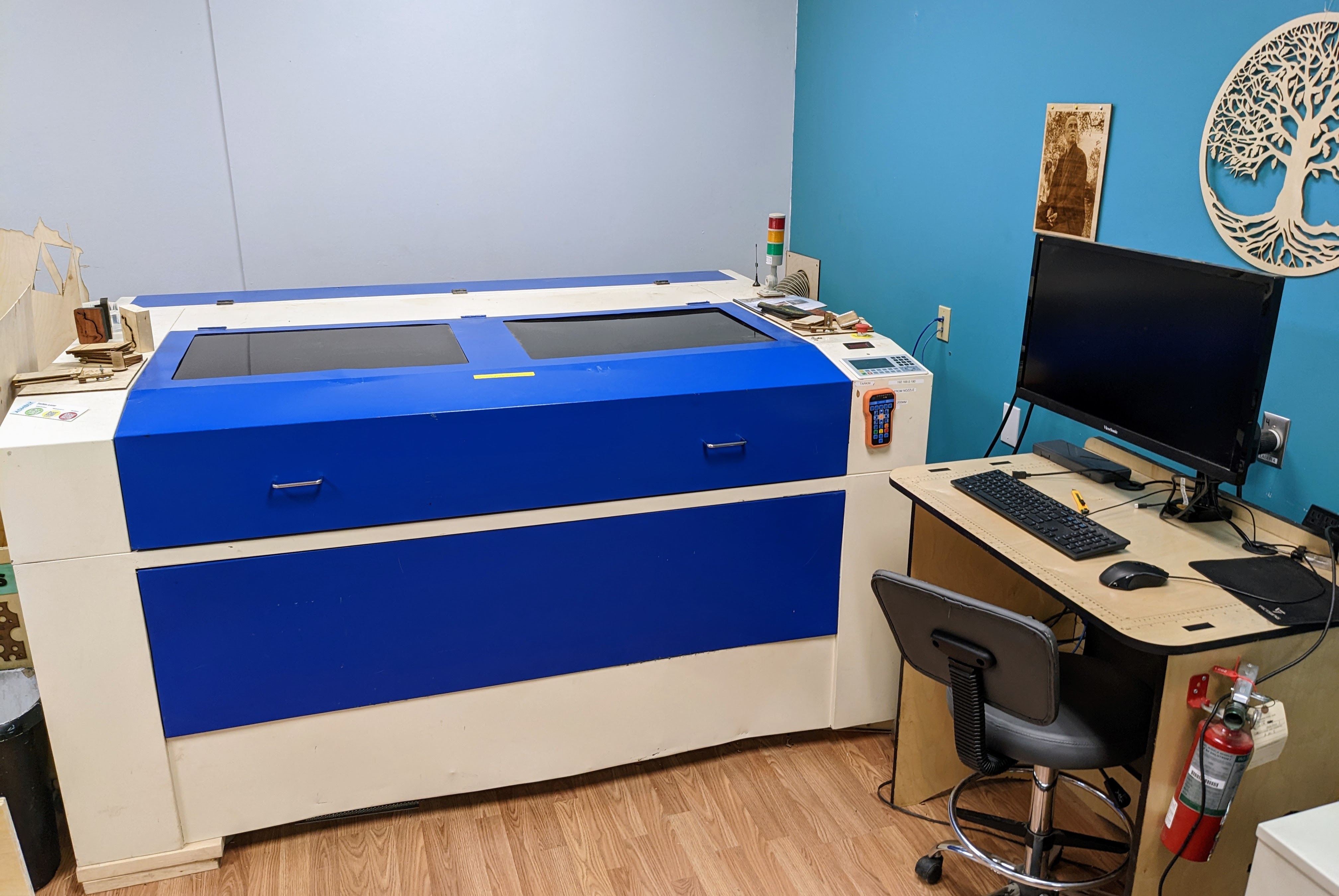
Tarkin is the new large-format laser cutter in the space, currently the most capable of our lasers for 2-d operations. It's a hot-rod custom-built laser cutter based on an RF CO2 10.6um laser and the latest in C-rail linear rails and a closed-loop servo-stepper motion system with a Ruida RDC6445G controller running Lightburn software. It features 225W of power on a 1.6M x 1.0 M (63"x39") cutting bed, powered Z, 16MP alignment camera, and air assist.
It's quite large and capable -- we don't think there's anything like it in central Texas.
Use as per https://wiki.asmbly.org/index.php/Covid_Policies#Equipment-specific_time_limits
![]() Members must complete the Big Lasers Class before using this tool
Members must complete the Big Lasers Class before using this tool
Setup
1. Locate Fire Extinguisher
Please locate the 2 HALOTRON fire extinguishers as you enter the laser room. These are the preferred extinguishers as Halon is a clean smothering gas that leaves no residue. The other extinguishers outside the laser room are ABC, which smother by spraying a great deal of baking soda powder that is difficult to clean out of the laser. These may still be used in an emergency, but the HALOTRON extinguishers should be tried first.
2. Main Power Switch
Powers on laser. Currently also powers on exhaust fan and air assist pumps, however, these may soon be moved to a different switch so they do not need to be left on all the time. If so, an interlock will prevent the machine from running if they are not also activated at that time.
The lowest switch operates an LED light bar inside the bed
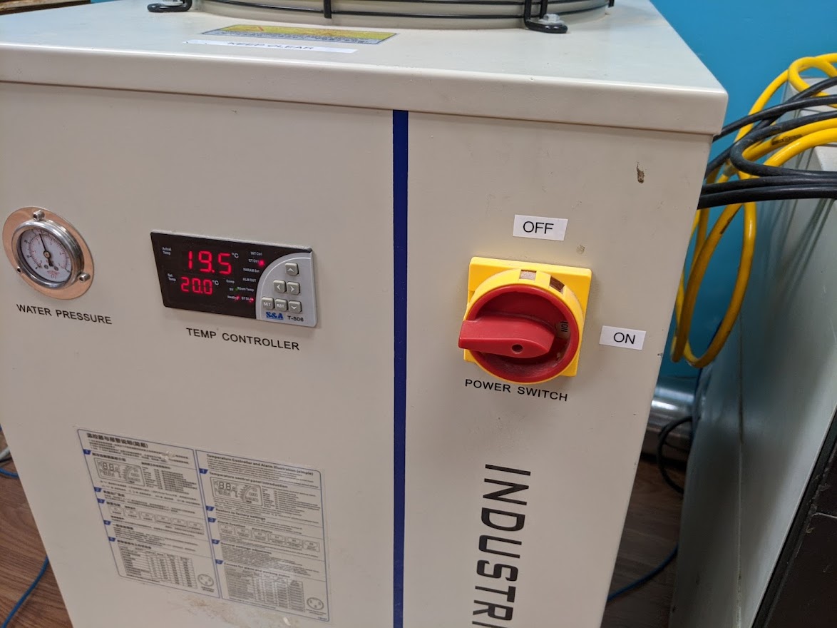
3. Chiller switch
Starts chiller, required for all work. The machine will refuse to run and give a "WATER PROT" error if the chiller is not pumping.
4. Locate E-STOP button
Backup safety feature, cuts power to Ruida, motor drives, and disables laser power supplies. The regular STOP button is preferred.
Once E-STOP is tripped, it will mechanically latch down and must be twisted 90 deg clockwise to allow it to release
The E-Stop button does NOT remove all power from the chassis. The chassis will be partially live unless all 3 plugs are unplugged from the wall
5. NEVER leave the laser while running
Important Terms
(just proposed for now, following documentation needs editing to use these consistently)
Machine bed
the physical machine's actual work area.
Control Panel (Ruida control panel)
the Ruida hardware panel on the physical machine. Small color LCD and membrane keys. Not to be confused with the Lightburn software running on the PC.
Material
your physical stock- a piece of plywood, acrylic sheet, etc. You'll be placing it on the machine bed and cutting your job on it.
Lightburn
the software on the PC for CAD, specifying what to cut and how, and has control for some live interaction with the machine. Your job is created within a workspace inside Lightburn.
Workspace
Lightburn's work area on the PC. This is the same as the machine bed only if you make the workspace size the same as machine bed size and operate in absolute coordinates. Otherwise, where your job is placed on the workspace is not necessarily where the job will be when you go to the machine bed, and your workspace can be declared in a different size than the machine bed. Note that in either case, your job (the actual content) will probably be smaller than the whole declared workspace, and cannot be located outside the workspace when you actually want to send it to the laser. Raster content cannot use the entire width of the workspace as it requires enough extend space on either side to decelerate and accelerate back. You will not know if it has enough extend space until trying to run the job at the machine.
Job
your content- vector/raster operations you want the laser to do. The location of the job on the machine bed is flexible and can be moved from the control panel, or it can be fixed. Your job exists in two forms- on the workspace (Lightburn software), and on the machine bed (physical machine). In the case of user origin, they may not be in the same place.
User origin
your job's origin. It is not used in absolute coordinate operation. The user origin also has two forms- it is represented on the workspace with a green square, and can move in relation to your job. At the control panel, you will set the user origin to the current head position with the ORIGIN button, which moves your job so that the green square will be at that point.
Vector Cutting
The most common operation, the goal is to cut out your shapes
Vector Engraving
The goal is to mark the surface with a vector, but not cut all the way through. Amount of burn per inch is limited by raising Speed and/or reducing Power to avoid cutting through
Rastering
The goal is to mark the surface, or produce a 3D depth carving. The head will move back and forth many times, and step over via Line Interval each pass.
Rasters may begin as a form of bitmap graphic, or a solid Fill of any closed shape
Fill
Fill is a special case for rastering inside LightBurn. It is a Layer setting to raster to fill in the closed shapes with a solid shade. It cannot do graphics or patterns and the Image settings do not apply.
Focusing
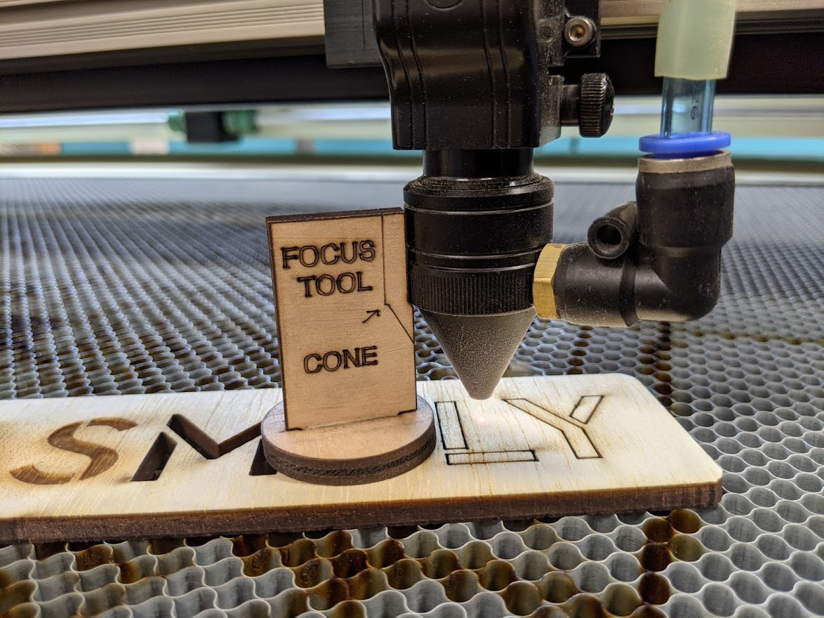
Focusing is currently done manually (this may change). For reference, the focal point is 6mm from the tip of the cone.
Although the head, like most designs, has an adjustable tube, we do not operate by adjusting the tube. Please ensure to tube is all the way up before continuing.
Place your material on the machine bed
jog the head above the material
Place focus tool on top of material as shown
Use the Z+/Z- keys to raise and lower the bed until the focus tool corner, as shown on the tool, aligns where the corner of the conical part of the cone turns into the cylindrical part.
Once you reach the proper height, nothing else needs to be pressed and you can continue to use the machine. The control panel will read out around "Z 3000mm". This number is not important. In cases where you need to deal with thick material, you may raise the bed from this point by as much as -5mm. If so, this readout can be used to measure simply by relative values. e.g. "Z 3002.7" after using focus tool. To achieve focus -2, press Z UP until the display reads "Z 3000.7"
Conversely, rastering time can be greatly reduced by lowering the bed after using the focus tool to increase the spot size and increasing the line interval by the corresponding amount. Lowering by 7mm corresponds to roughly 0.5mm line interval and 14mm is 1mm line interval.
Quirk: The machine bed can shift laterally by several millimeters in the X and Y, when Z is moved. Please adjust the Z BEFORE making any precision placement of origin. Until this is fixed, the Z should not be moved to different places within a job as the XY alignment may shift.
Origins
Tarkin's origin is commonly set in one of three ways:
Absolute coords
using a workspace the size of the machine bed. The location of your job is fixed and the user does not operate the ORIGIN button on the panel, as there is no user origin. The camera may or may not be activated
User origin
Your material is placed anywhere on the bed that is convenient, and the user moves the head to the desired origin point and presses "ORIGIN" to work around that spot. In this case, it is not important where the user places their job on the PC's workspace, or that the workspace be of the size of the laser's bed at all. Lightburn will automatically create a bounding box around all the user's job within the workspace, whether or not it is designated to be sent at that time. The user can specify the work origin to be in the center, any of the 4 corners (top left most common), or 4 sides (uncommon). It is possible to place the origin in a way that the job will eventually run off the machine bed, this will result in "FRAME SLOP ERROR" and will not run. Correct the origin position and use the FRAME button to verify its bounding box. Note that moving your job around the machine bed via the user ORIGIN button does not move your job on the workspace.
User Origin, CENTER, is the safest option if you are using clamps. The head will return to that origin at the end. So, that origin point being in the center of your job, no clamps should be in the way. However, the head will of course have to travel in a line from wherever it is to the start point, so if the user origin was not set correctly or the head is for some reason located outside the job before starting, it might still be possible to strike a clamp. Currently we do not think head strikes will be a big problem for the machine, mostly it would mean your material gets knocked around and your job could be spoiled.
Camera-placed absolute coords
Your material can be placed anywhere visible to the alignment camera, the Lightburn workspace is set to the full machine bed size, the user jogs the gantry out of the line of sight (not obscuring your material), and then Lightburn takes a camera snapshot of the machine bed that shows up as a graphical background with your material on the workspace. The very rear of the machine bed is not visible to the camera for alignment purposes, as the lid is hinged closer than that. The user moves and aligns the vectors/raster job across the workspace so it is over the actual material by moving the job in XY and, if necessary, rotation and resizing may also be done. Lightburn will automatically change to absolute coordinates in camera mode, and the user does not operate the ORIGIN button. This method can also be used for hybrid work- for example, color printing paper graphics that were glued to plywood earlier, this material is then placed and aligned via camera and cut out into desired shapes with the laser, or an existing manufactured object is placed on the bed and the job aligned over it. There is no auto-recognition of printed registration marks, but printed registration marks do make alignment easier and more accurate. Another example might be a unique horizontal slice of a tree can be traced and artwork can flow with that arbitrary shape in size and alignment. So far, the accuracy has been better than 2mm, and may be improved with further calibration.
Power Settings (in Lightburn layers)
Lightburn has a sizable and growing database of known-good values for cutting and rastering on Tarkin, listed by material. Feel free to use them, but these can only be created or modified by admin. If you want a new entry, please submit the parameters and if possible a piece of that material and we can include it. Pearl will also have a Lightburn material database after it is converted to that controller, but it will have different values as the beam's power is different.
In general, if you have a material which is not listed exactly, scale speed and/or power proportionally.
e.g. if you only had a setting for cutting 6mm acrylic but you have 8mm, you need about 8/6= 1.333x the "burn" per mm. First off, if the power is not 100%, scale up the power- however, for most cutting we already max out the power and increase speed to the max that will still cut cleanly through the material. So the existing setting might be 6mm acrylic, 100% power, 35 mm/sec. In general you would scale proportionately- 35 mm/sec for the thin, fast 6mm divided by 1.333x gets us 26mm/sec on the thicker, slower 8mm.
The machine's top axis speed is set well over 1500 mm/sec, but this is not likely to be important for vectoring as this sort of speed is not commonly used. If the user's job asks for a speed higher than the machine can travel, the machine will limit its speed and proportionately scale back the % power to deliver the same energy per mm of length.
In general, Tarkin should be used to cut at 100% power. The amount of burn per inch is controlled by increasing the Speed parameter to the fastest travel that still consistently cuts through the material.
In cases of very light cutting (paper), vector engraving, or rastering, it is necessary to reduce power from 100% since it will cut all the way through the material even with very high Speed.
To test new material, the simplest thing is a line 20mm or longer. Less than 20mm may not get into constant-velocity mode and does not accurately represent the primary cutting ability.
Multiple passes are NOT useful
Very light vectoring such as text or outlining should have Override PWM clicked at 1KHz. [TBD: photo of prob]
Fill/Grayscale Raster Settings
In most cases we will not use 100% power. This is so much burn it could go all the way through the stock.
Line interval is equally important with power in determining burn depth, assuming your line interval is below 0.175mm thus not producing gaps between lines. If we halve the interval- thus doubling the vertical number of burn lines per mm- the fill will be twice as deep for the same speed and power setting. Also takes exactly twice as long, thus there's little reason to do this instead of raising the power which takes no extra runtime.
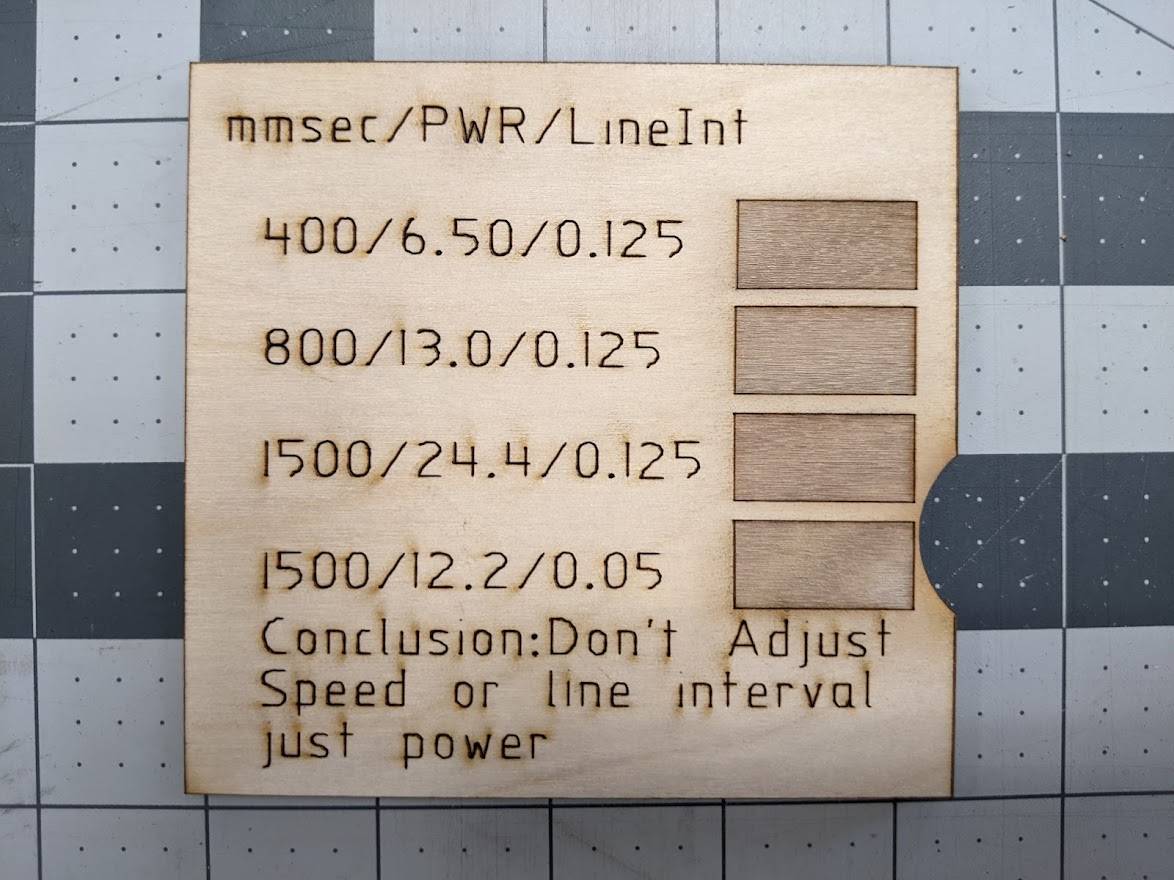
So, usually we're at 800 mm/sec or 1500 mm/sec, 0.125 mm line interval, and exclusively using Power to control burn depth.
These all look basically the same and have similar depth. 400mm/sec takes twice as long to cover the square over 800. These speed changes have no benefit.
Changing line interval from 0.125mm to 0.05mm takes 3x longer, but gives the same look. The fine-line-interval approach generally has no benefit below 0.125mm.
Why is 800 and 1500 being lumped together? Well, 1500mm/sec is a big timesaver on WIDE rasters, like >500mm. But the high speed requires a larger fixed clearance to the end of the rails (about 100mm "extend space") and also a larger fixed waste-of-time spend braking and reversing each line, regardless of the width of that line. With a 50mm wide raster, 1500mm/sec will not be any faster than 800mm/sec anyways, as it wastes so much time per line in extend space space and gets minimal benefit in moving twice as fast over the 50mm it actually burns.
Simple Bottom Line: 800mm/sec 0.125mm line interval for smaller Fills (or grayscale), and adjust ONLY the power for your depth of burn. 1500 mm/sec for larger Fills. Adjusting for lower speeds or smaller line intervals will not produce any different look than you could get with the right power level, they just waste time. The Line Interval can be increased to about 0.175mm, but this can produce a slightly wavy bottom and a higher number will leave visible rows as there is no overlap at all between lines.
Rastering
MAX RASTER
Rastering limit is 1500mm/sec. In general, rastering at 1500mm/sec is a good choice. This requires approx 100mm of Extend Space on either side. Slower settings are fine (suggest 800-500mm/sec min) and may actually get done faster on very narrow raster jobs as it greatly shrinks the amount of extend space travel needed. However, for wider raster tasks (>250mm) max raster will save substantial time.
Types of Rastering:
FILL
just marking/carving out even blocks in CLOSED VECTOR OBJECTS. This is not the IMAGE mode and does not apply to bitmap images. Line intervals <0.15mm cut deeper (typically not of value, just slows down job). WARNING: FILLS created by making a rectangle and using "LINE+FILL" or just "FILL" DO NOT use the grayscale or dithering parameters and should not be used as a test to calibrate those modes. The Materials Library raster settings cannot be loaded for a Fill, it will not go into those parameters.
Also, in Lightburn a Materials Library entry for a material uses the same "Line" parameters for both cutting and the "Fill+Line". All the normal library entries are for cutting and should not be switched between these modes. Materials Library entries labeled "Fill+Line" are only for this mode and NOT cutting- they have no material thickness and are generally flexible on what material it works with. These are a starting point and the user is free to copy to their layer and tweak the depth via the POWER parameter.
Again- Although both FILL and IMAGE are rasters, FILL is only a technique for CLOSED VECTOR OBJECTS. Settings created for FILL (speed, power, line interval) will not be used if we select a bitmap, that will convert the layer to IMAGE which has different settings which are not even visible until selecting a bitmap pushes it into IMAGE mode. Likewise, IMAGE settings will not be used if you select a closed vector object and switch to FILL.
GRAYSCALE 2D
Laser power is modulated by grayscale shade. Goal is not depth, but shading. Line intervals <0.15mm cut deeper (typically not of value, just slows down job). Grayscale works if your material can show good dynamic range (shade darkens proportionally with beam). Dynamic range of material must be investigated carefully- for example, plywood veneer may start light, burn darker with more beam, but past a certain point we cut through the veneer and briefly get a red shade from the glue and then a totally different shade from an inner ply. This would be a very poor dynamic range to allow the power to pass the point where it becomes darkest.
Some materials such as black marble would have an inverted dynamic range- unburned is black, but it becomes white when burned. In this case, Invert Image button may be desired.
Note: grayscale 2D is not effective with most CO2 lasers and most lasering user guides advise against it. Tarkin is NOT an ordinary CO2 laser in this regard and does amazing things! It requires careful tuning, but produces notably superior detail in the final result.
GRAYSCALE 3D RELIEFS ("depth map")
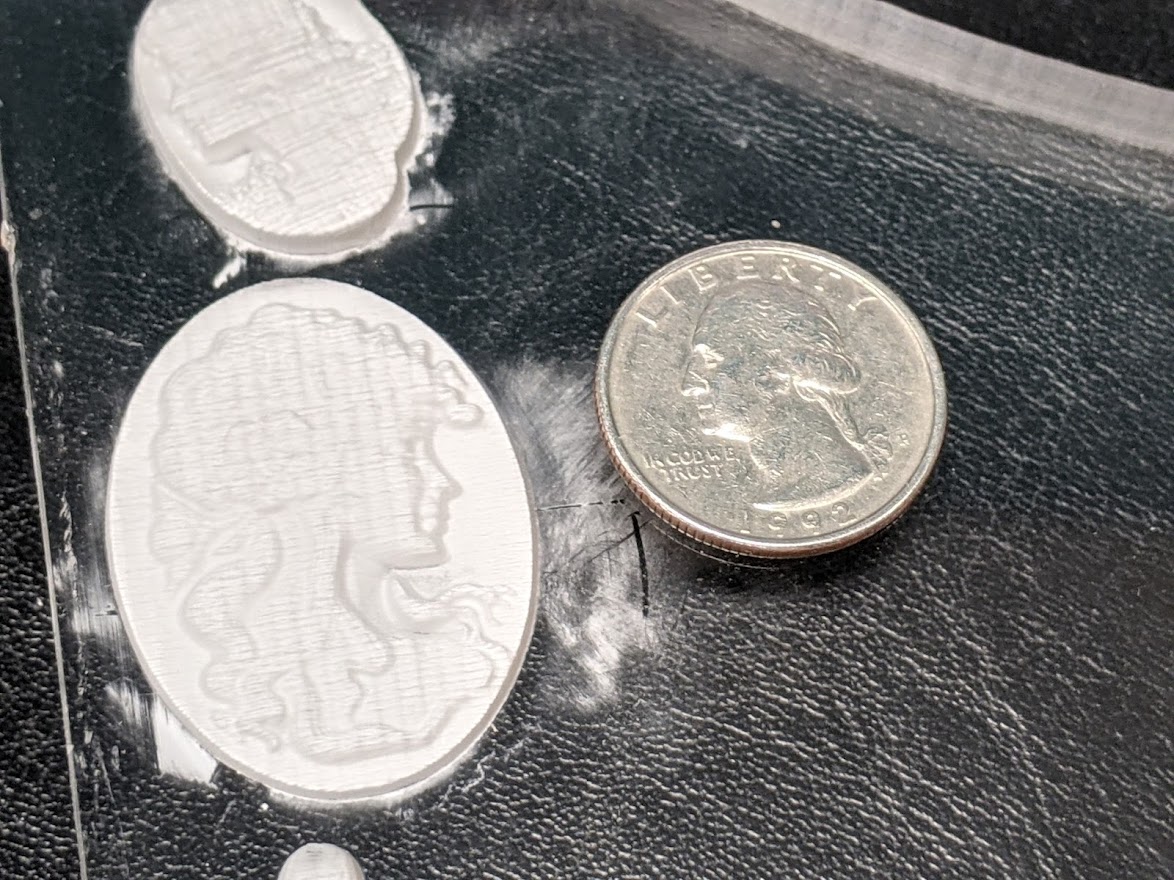
Same mode, but different goal. Laser power is high enough to carve into the material. We are not trying to produce varying shades, but varying depth. Works very well with wood and acrylic. Homogenous materials like acrylic have a very constant power-to-depth ratio. Wood, however, has bands of hard and soft grain. The higher density of the hard grain bands leave a shadow that will not be cut as deep. This is part of the character of 3D cutting wood. This also affects all FILL.
A bitmap used for this purpose is called a "depth map", but it is essentially a grayscale image with depth represented as darker pixels. But this is still fundamentally different from a picture- if a photograph of a light-skinned person were cut as a depth map, it would appear grossly distorted- the whites of the eyes are highest, the hair would be cut deep, and pupils cut deepest. [TBD: example of distorted use of 2D image]
If you want to avoid creating obvious unburned areas where the shading is very light, set MIN POWER parameter >0%. While in the raster area, this rescales the laser output. Black is MAX POWER %, white is MIN POWER %. In acrylic we often allow the lightest shading to remain untouched clear acrylic for contrast.
3D may utilize smaller line intervals effectively, it will just burn deeper as lines overlap. However, in general increasing the power may be more practical.
STL model files can be turned into depth maps via https://www.meshlab.net/
Note that STL files generally need to be designed as 3D reliefs to produce good results. Reliefs are an artistic style that trick your perception into seeing a much deeper scene than the actual material. Simply flattening a 3D scene by 99% may not yield usable reliefs.
3D reliefs have difficulty scaling. 15mm acrylic cut a max depth of 8mm might produce a great quality image when rendered in a 100mm x 100mm frame. However, when increased to 200mm x 200mm, the same 15mm acrylic cannot be burned twice as deep. If burned to the same depth, the image will be relatively flat in the Z dimension. In order to maintain the original scale, the acrylic stock would need to be 30mm thick!
Reliefs in clear acrylic look MUCH better when mirrored, the shading changed to "negative image", and cut from the BACK side. When edge lit, the look is fantastic!
DITHER/HALFTONING 2D
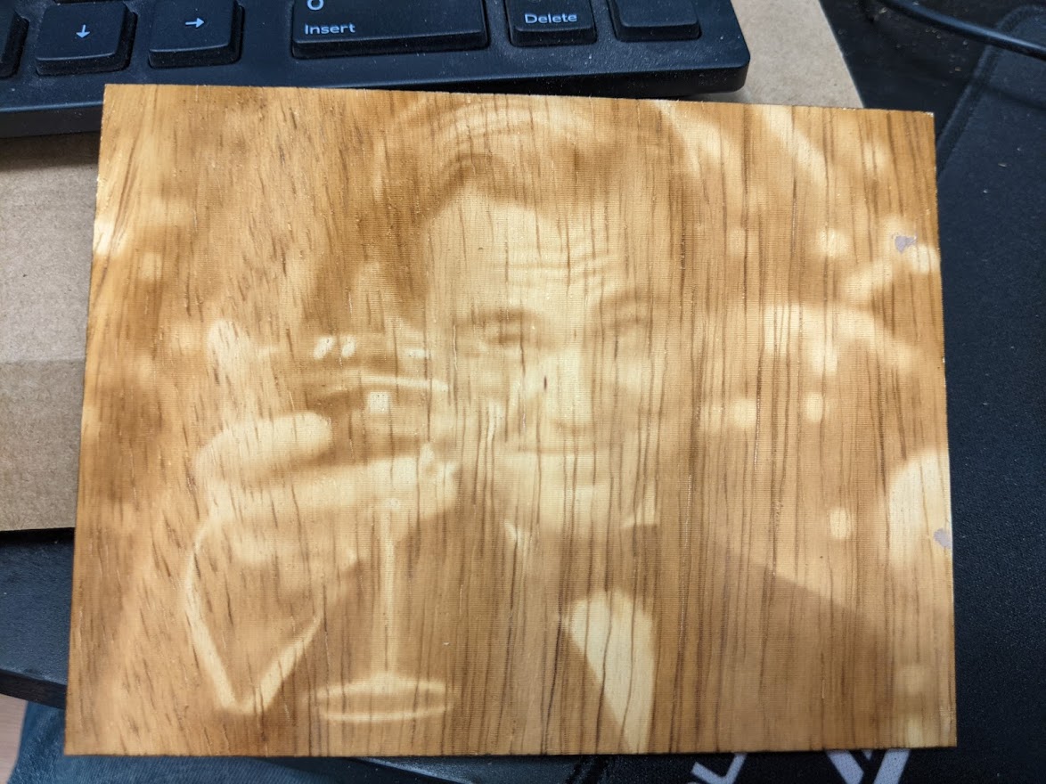
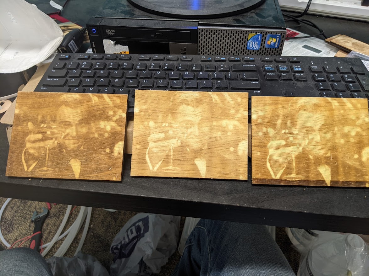
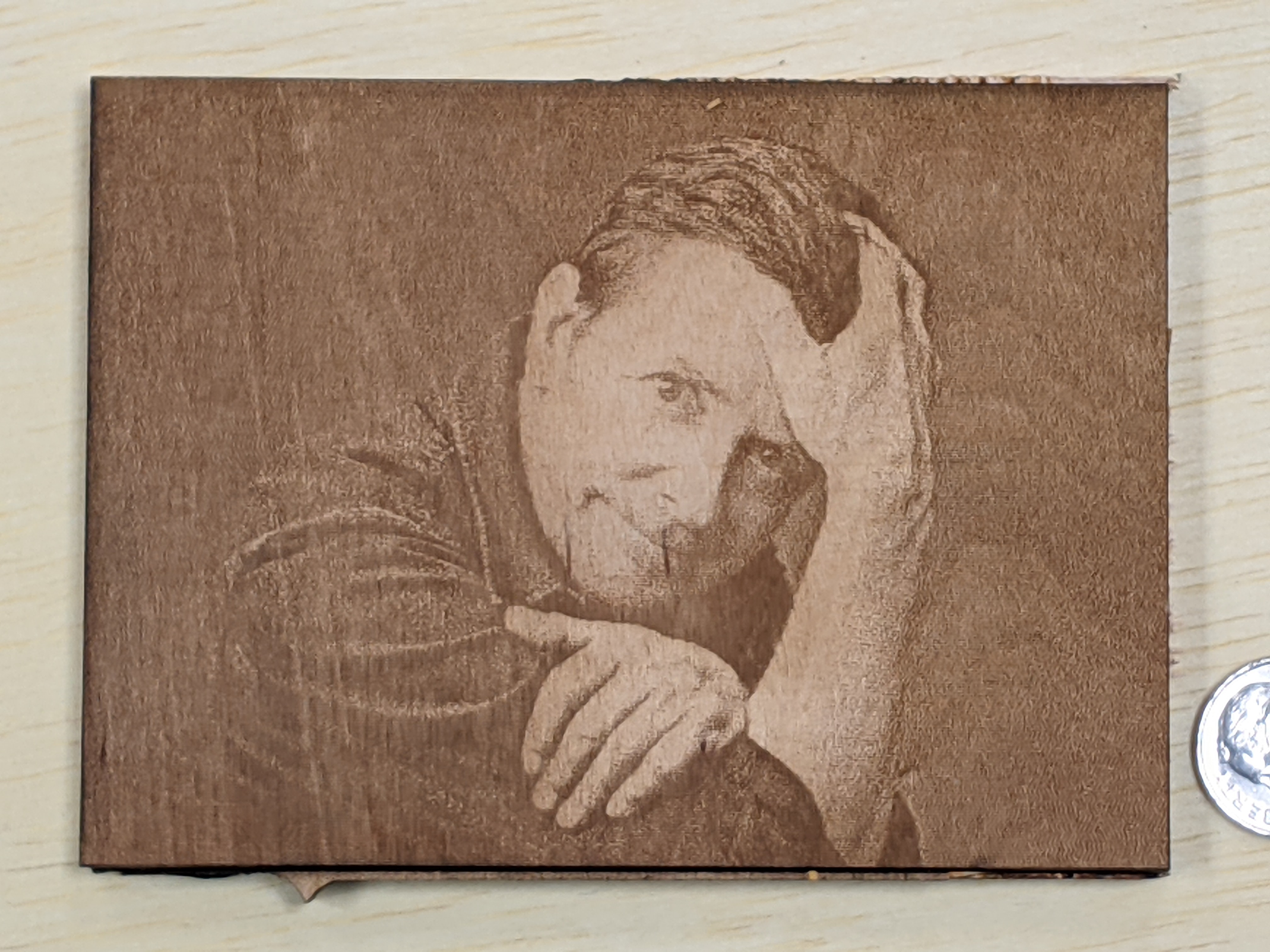
Most common choice for photographic work. The basic scheme of dithering is we have the original unburned surface and burned "brown" areas and nothing in between. The appearance of "shading" is created by a ratio of these, not by turning the laser intensity up and down.
The beam is often turned down quite a bit- 8% on wood is a good starting point.
Proper Line Interval in Image Dithering/Halftoning
Dithering/halftoning MUST use correct Line Interval that matches the beam width.
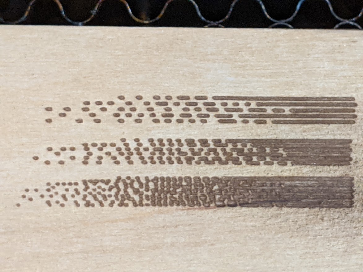
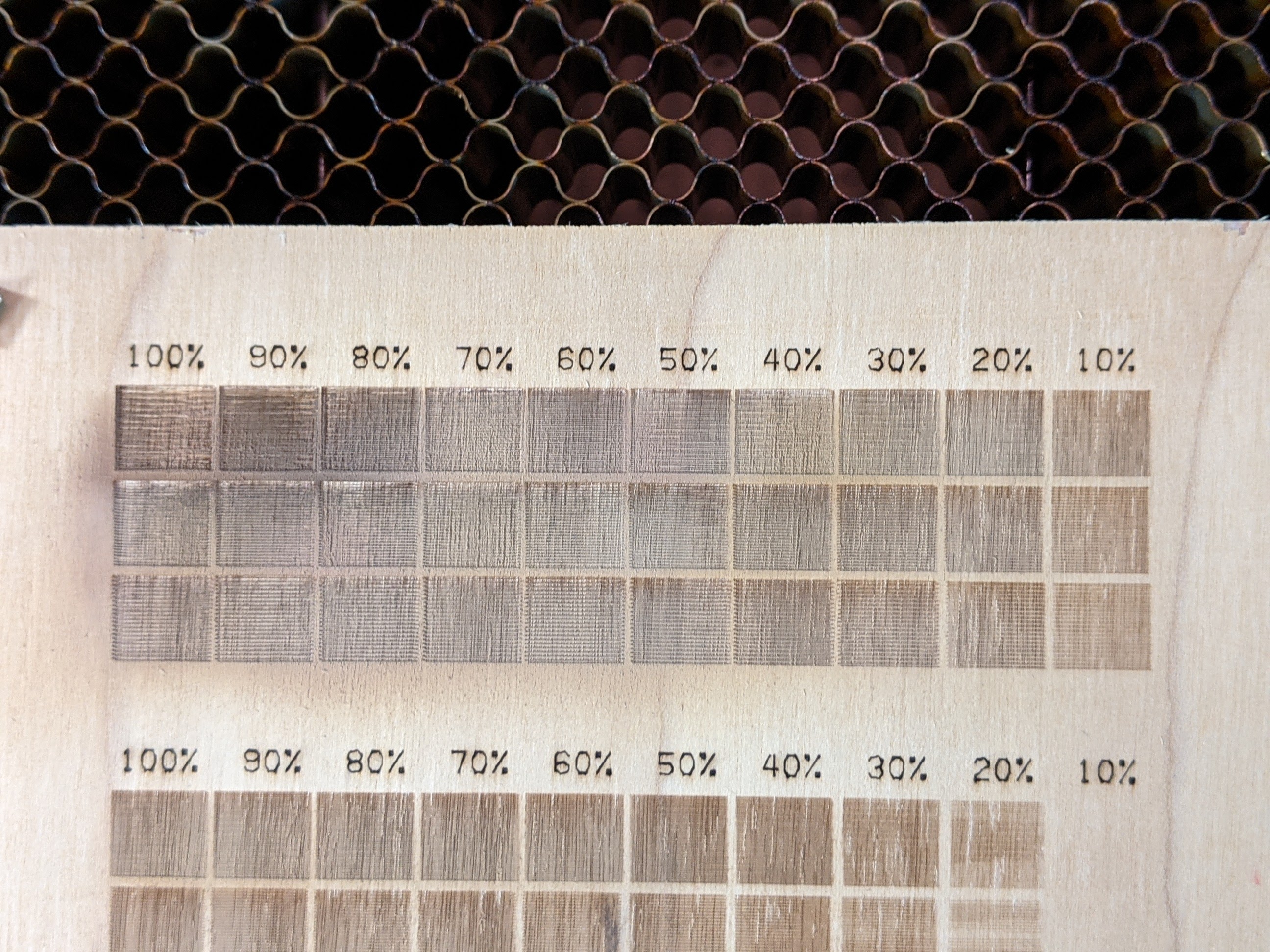
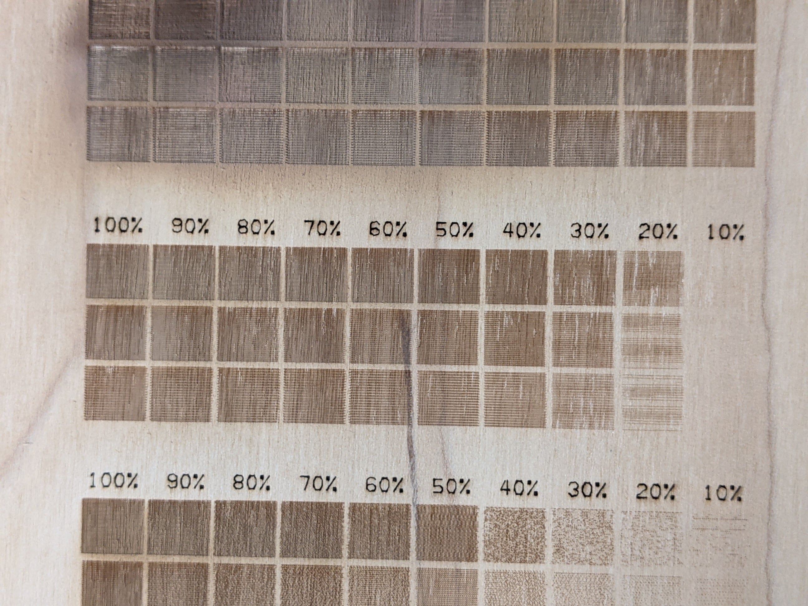
The first gradient shown has line interval set 33% too high. Visible white lines separate the dithering pixels regardless of the image's grayscale value at that point. At a distance where dithering pixels are not apparent, this reduces the deepest color change that can be achieved, and also the level of detail (resolution) is decreased.
The lower gradient is too low, 67% of what it should be, and this has mostly broken the dithering scheme. The rows are overlapping, resulting in completely burned-out areas past around 50% gray; there is little midrange.
The middle is just right! Raster lines abut but do not overlap.
The width of the burn mark at good focus is approximately 0.175mm-0.100mm, it narrows with higher speed (less burn) so recheck the line interval after changing power.
Rastering with Focus+
Large rasters benefit greatly from running out of focus to enlarge the spot size and reduce the number of raster lines needed.
Running the Z lower will widen the spot in a predictable, consistent way. +15mm will yield a 1mm spot size. Start by focusing for the top as usual using the tool, note the value of "Z" on the panel, it should be around 3000mm, but this is only used as relative value. Write down the number for the focal point and add 15mm to it- e.g., if the panel reads 2998.2mm after setting Z with the focus tool, you would jog down to 2998.2 + 15 = 3013.2.
The spot is widened to 1mm at this point, so the Line Interval will be set to 1mm. Since the beam is spread over a larger area, it will be able to use all the power without blasting through the wood. 100% power 1000mm/s 1mm Line Interval and Jarvis dithering yields this. Despite its massive size, 839mm x 644mm, it was done in just over 12min.
Proper Line Interval In Fill or Image Grayscale 2D/3D:
Depth comes from 3 factors. The first 2 factors are the same as cutting- doubling the speed halves the burn depth, doubling power will double the burn depth. But Fill comes with an additional factor, Line Interval. Unlike Image Dithering, this parameter is practical to adjust for effect, but only in rare circumstances. Halving the line interval means twice as many passes per mm. Like halving speed, this will take twice as long to run. However, Line Interval has an upper limit of about 0.15mm before the raster lines do not overlap anymore and it will not remove a solid volume, but individual lines.
In most situations, we are seeking to limit the depth, not maximize it. As such, Speed should be 1500-800 mm/sec, Line Interval should be 0.1mm-0.15mm, and the depth is tailored by reducing Power significantly below 100%.
Determining Best Raster Power for Image or Color-Change Fill
Some jobs cutting with the "Fill" seek depth, not color change. Such as carving out block lettering with depth for signs. However, a goal might also be color change, and this guide applies to this scenario.
The goal of most grayscale or dithering is to produce the desired color change- typically the deepest color change possible. Initially, color typically deepens with more power. However, after a certain point the material may instead become lighter or change color entirely, and it may not be clearly evident until the wood is being cleaned of debris. This can happen because wood may pass a point where it starts to disintegrate into char and instead is removed entirely. In plywood, this may even reverse the color deepening trend because a veneer or ply of one type of wood is penetrated, exposing a different layer.
The possible color change varies based on the material type. Wood gives much more dramatic color changes when pretreated with a light spraying with a contrast solution of baking soda, a drop of dish soap, and water and allowed to fully dry before lasering (this may take hours so best to do ahead of time). Some have tried boric acid solution, however, while it initially appears even blacker, it is mostly a char that comes off.
Tarkin's Material Database has examples of raster settings as well for different materials at focus and and different focus+ points. If you wish to generate your own, here is a suggested procedure for creating new settings.
Tarkin is VERY powerful. At focus, most plywood yields optimum color change with 1500mm/sec 8% power. If we use focus+ methods to increase spot size and yield a faster raster, the optimum power will increase as its energy is spread out over a wider swath. The limit is roughly focus+15mm which yields a 1mm line interval and will take 100% power. This is excellent for huge graphical burns.
Are there other speeds? Yes. but we are already speed-limited, not power-limited. For example, 750mm/sec and 4% power should yield a virtually identical burn, but this job will take twice as long so there is no clear value to it.
If instead you want to develop your own settings, possibly for a focus+ situation, here is the method:
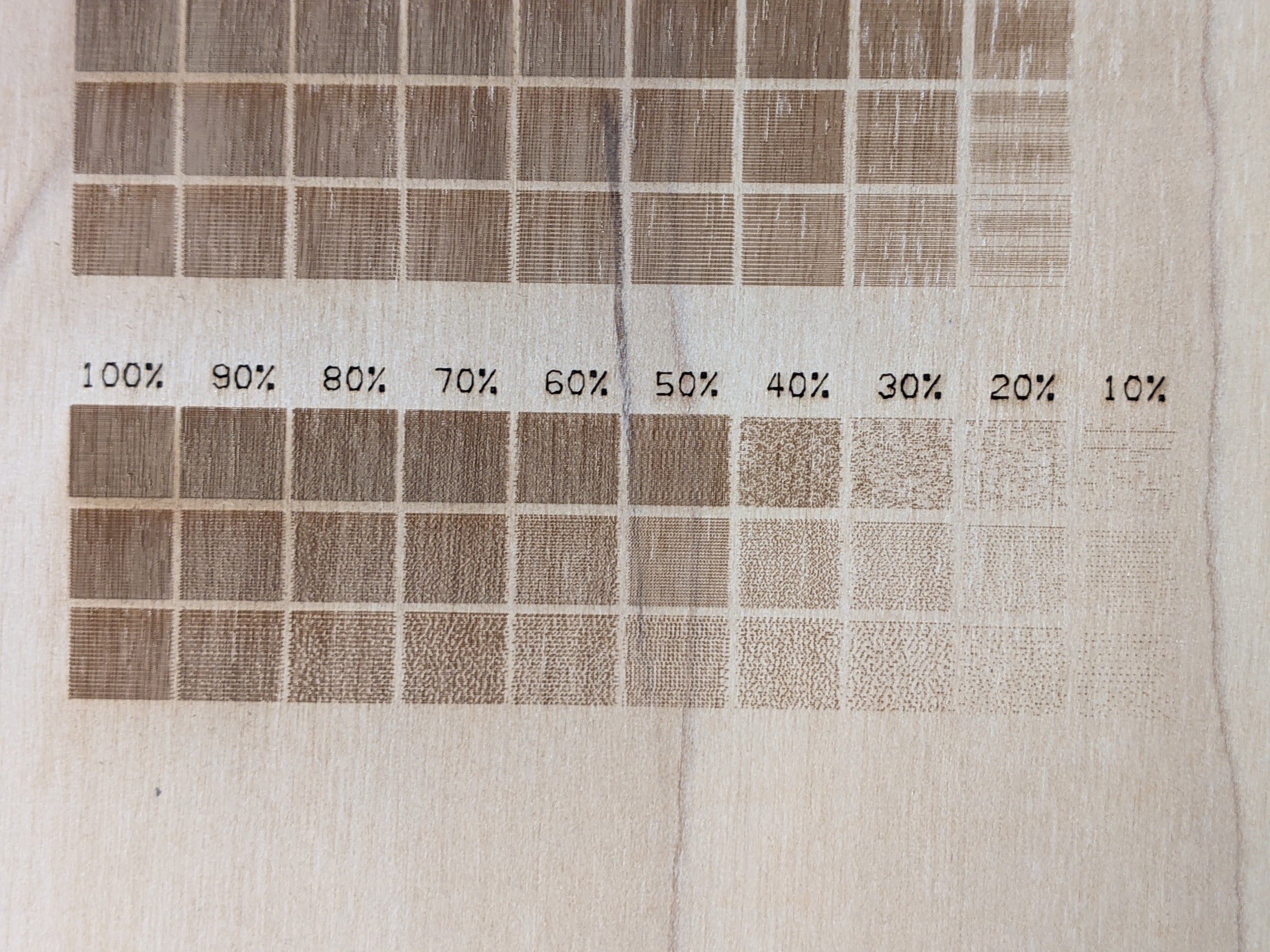
Load Lightburn project "tarkin_raster_calibration.lb2", and try with the enclosed power settings on a test piece of your material. This essential testing step for determining speed, power and line interval burn settings that must operate in GRAYSCALE MODE, EVEN IF YOU ULTIMATELY INTEND TO DITHER. At best focus (not focus+), line interval is known to be roughly 0.15mm, so we have a 0.1mm, 0.15mm, and 0.20mm line interval rows here to verify.
We increase the power in 10 steps from left to right columns, and show the color change as shading increases the beam to the full power setting. Although done in grayscale, this calibration is necessary for dithering modes as well.
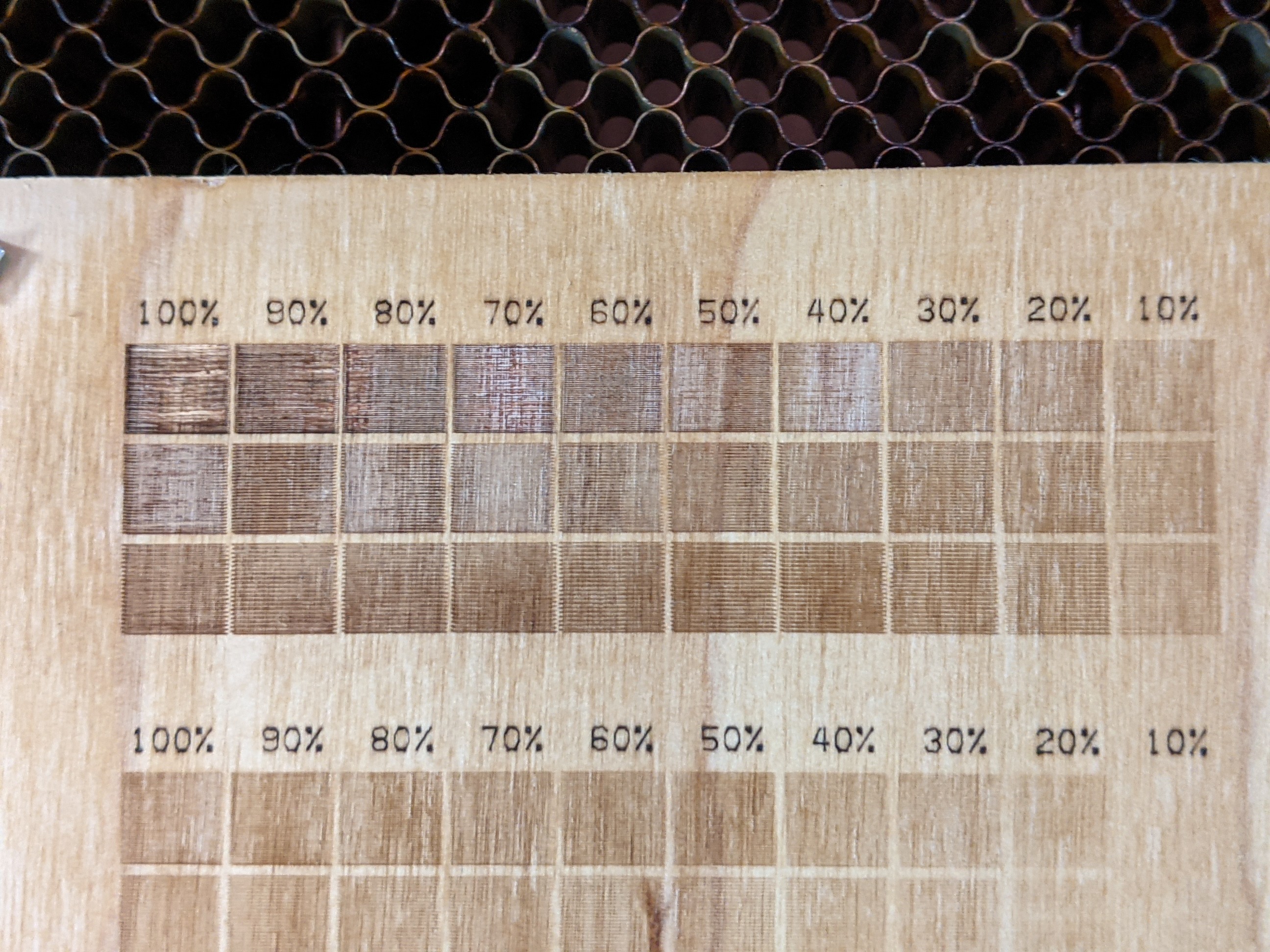
This is a shot in the dark with 1500 mm/s and 40% power. The % in font represents the fractions of the 40% power. The rows represent 0.10mm, 0.15mm, and 0.20mm line intervals. At a distance, the color seems similar, but the blasting of soot at the higher powers is a bad sign. After a cleaning of loose, dusty soot particles, we have this:
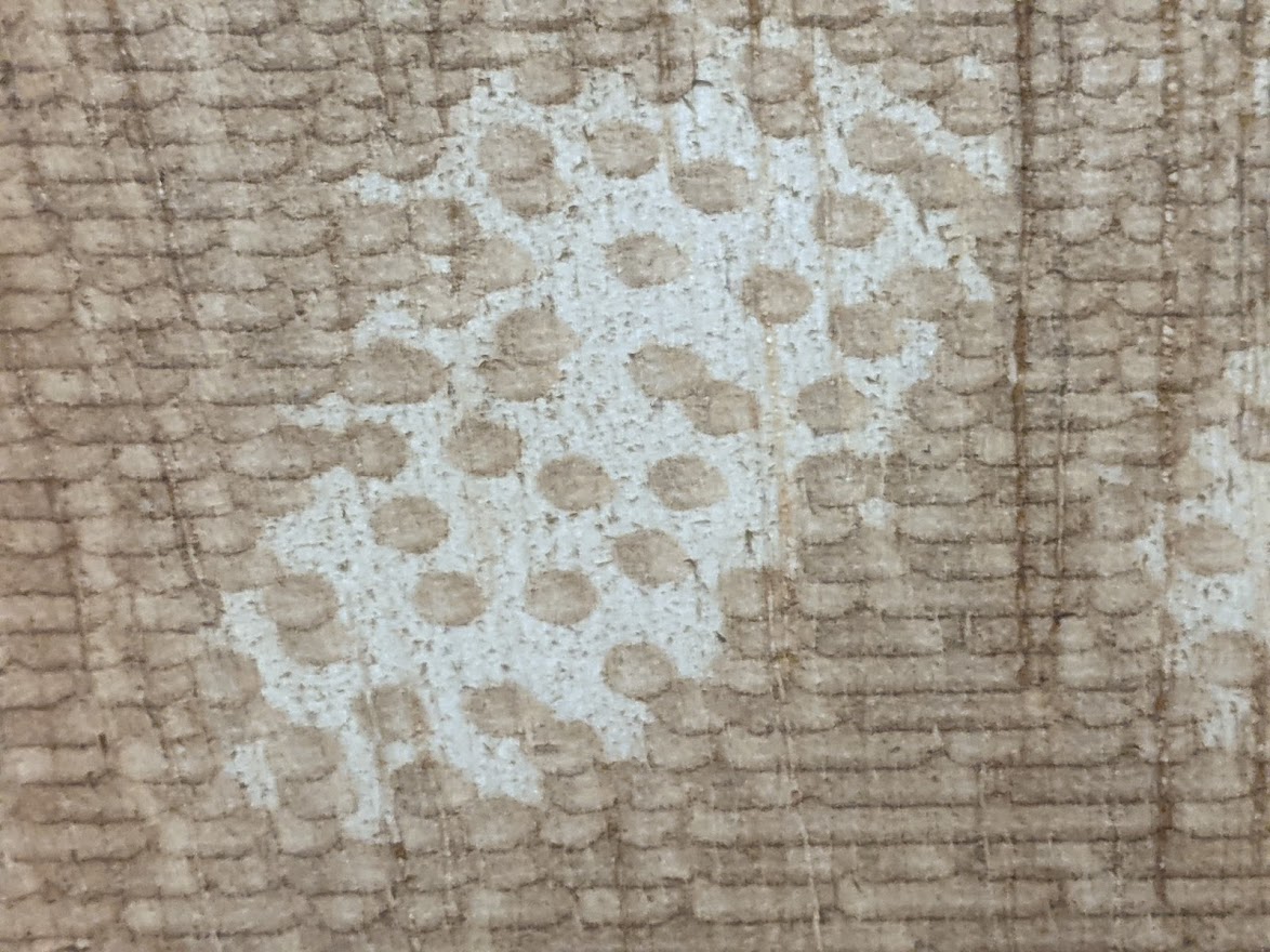
Overburn apparent on cleaning. The top ply stopped getting darker after the first couple of panels. This is OVERSHOOTING the power, removing the surface ply entirely and exposing the glue and inner layers which are somewhat lighter and not even brown. The reddish look is the glue layer. Let's back off from the 40% power down to 1/4 of that, changing 10% power=full scale.
The line interval is appearing to favor the 0.15mm middle row, but let's look closer.
Now the scale has 10% power for the 100% of grayscale, total black square of the original graphic. But, wood being wood, our dynamic range is poor. The 80% of that shows approx the point of max color change, a net of 8% power. At this point, the strength of the beam produces a beam width that hits the sweet spot of no gaps but minimal overlap at 0.15mm. That should be our line interval for this net 8% power, let's verify in the next step.
Now that we know 8% power 0.15mm line interval produces the best color change, let's change this entire graphic from grayscale to stucki dithering, which will decide when to fire or not based on shade, but when it fires it will always be at 8% power 0.15mm
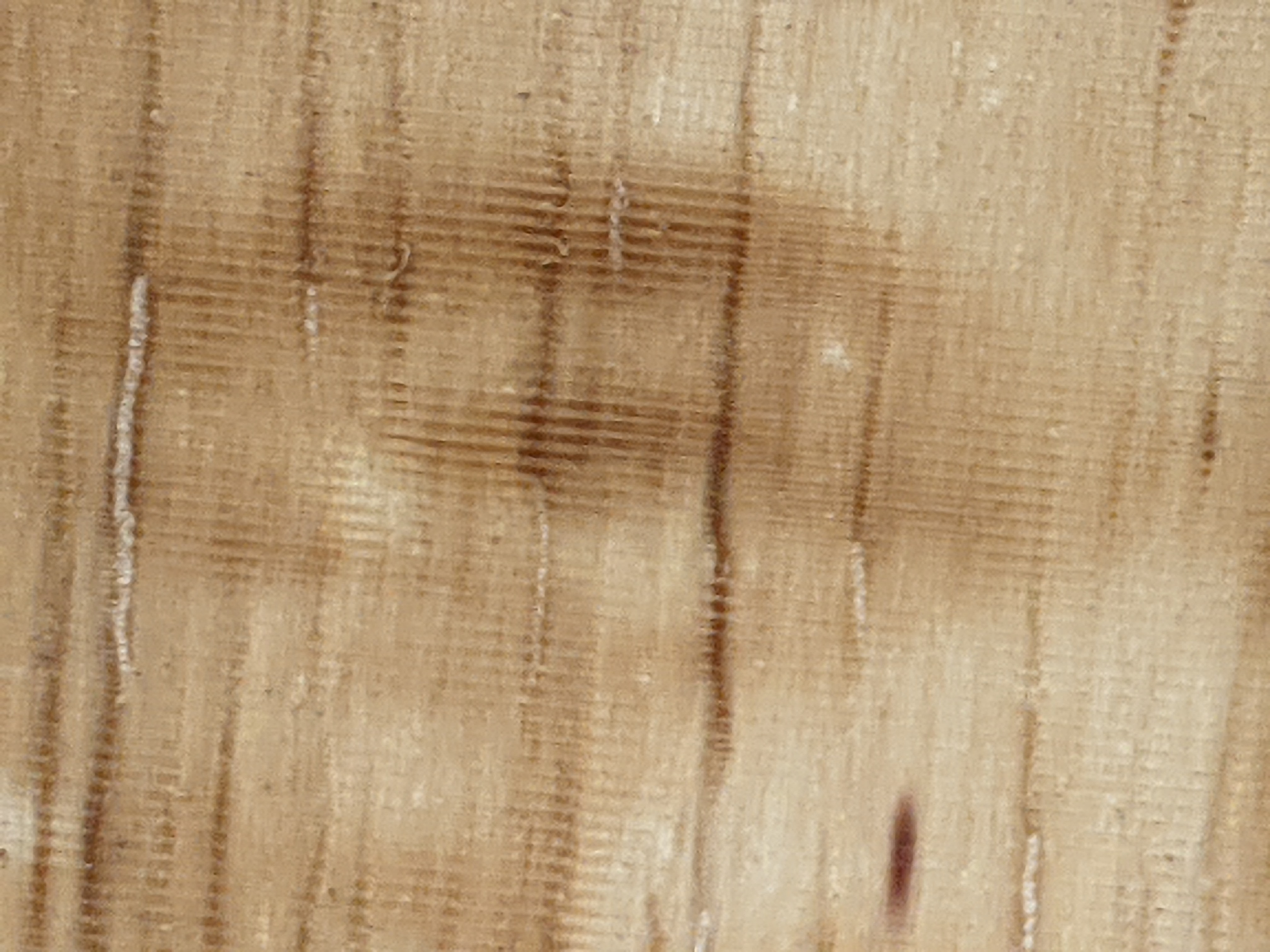
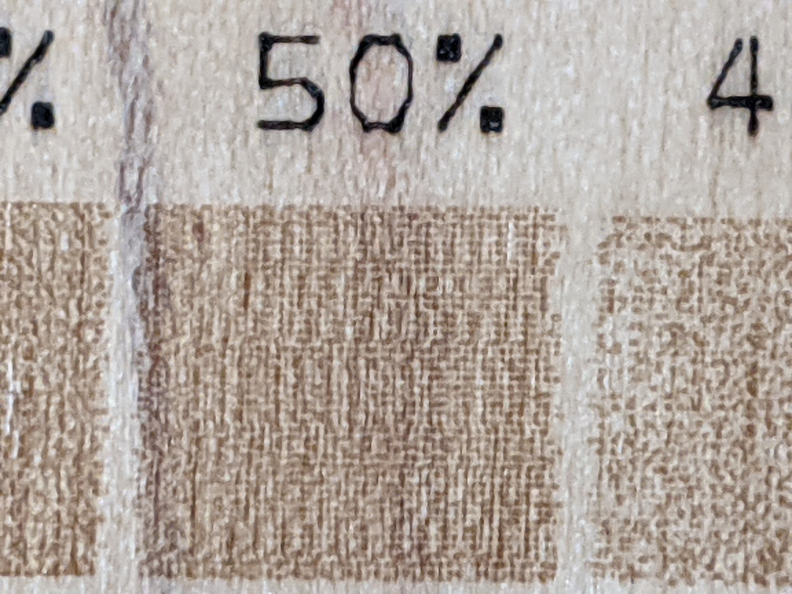
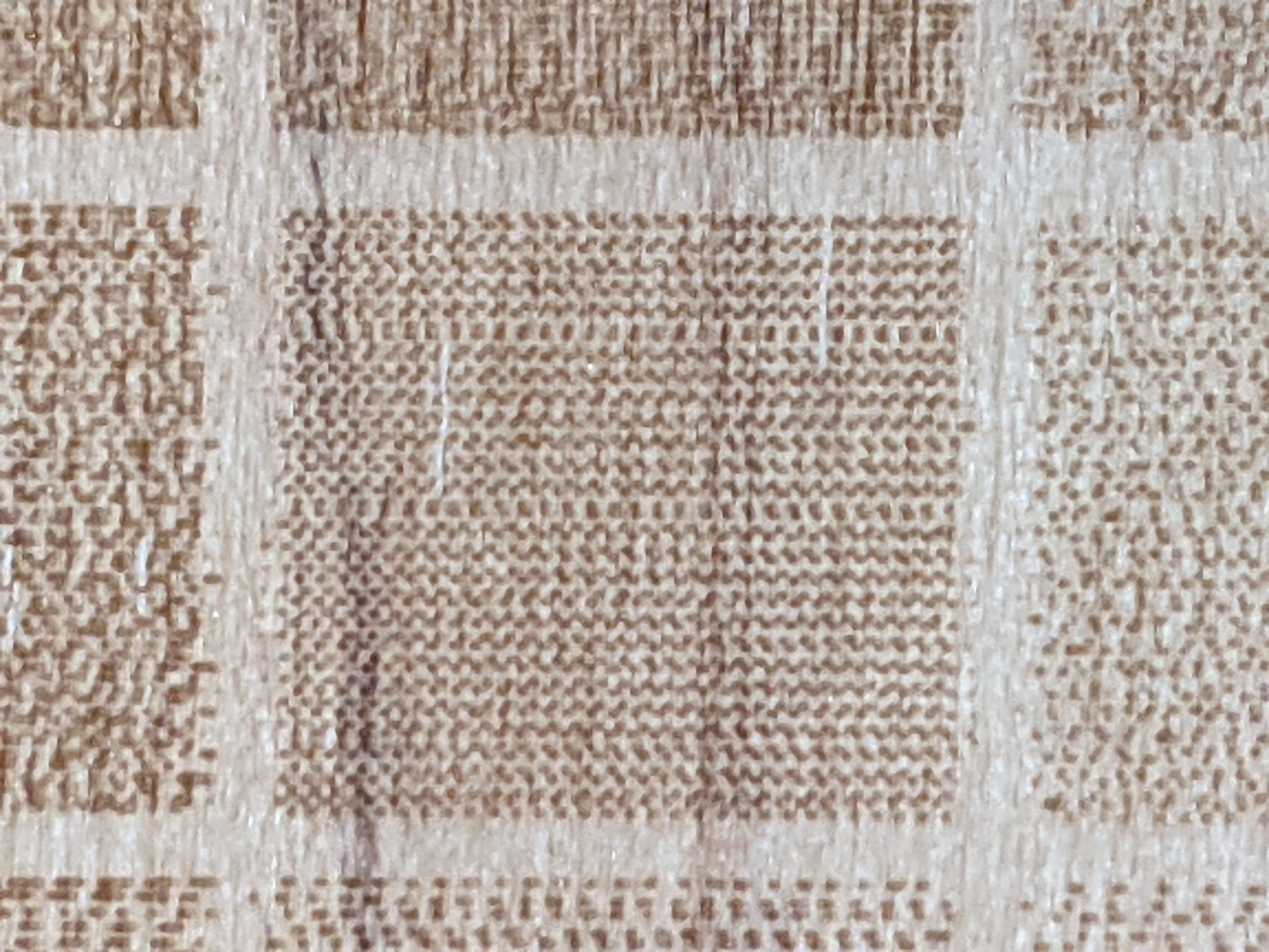
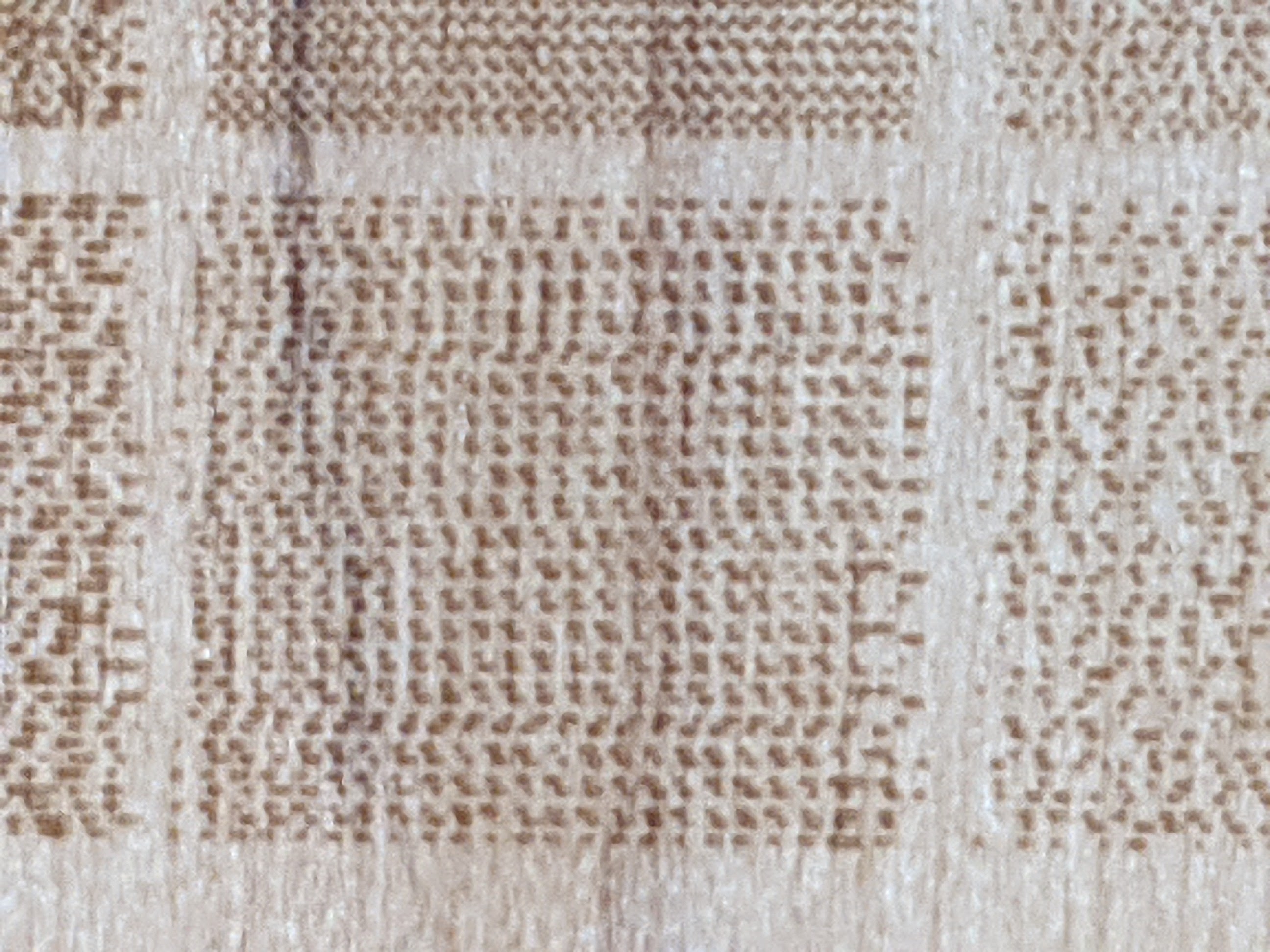
Let's take a closer look at the raster's lines
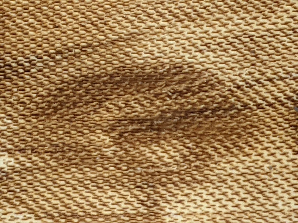
0.1mm line interval, these rows are too close and overlapping the dither patterns, breaking the effect. Everything starts to look a similar shade of brown as the rows of pixels overlap, more so at the deeper grays. So the dynamic range is all in the lower % and then turns all similar-looking brown after 50% gray.
0.15mm line interval at 8% power= net 5%. The columns are just short of overlap. This is a correct raster target!
On the other hand, 0.2mm line interval is showing gaps between rows. The line interval is too wide.
We have successfully determined our ideal numbers a dithering raster for standard focus- 1500mm/s, 8% power, 0.15mm line interval.
Some materials such as black marble start out as dark, but turn white when etched by the laser. In this case, NEGATIVE IMAGE button is used to tell the machine to fire the laser for the white part of the image instead of black.
Adjusting the image for rastering
At this point, the optimum burn settings determined and and should NOT be adjusted at all to change the appearance.
Rather, let's look at the original bitmap image itself. Select the image, then Tools->Adjust Image. There are sliders, dithering methods, and live, zoom-able preview of the image. Any changes here are DYNAMIC- it keeps the original bitmap and a list of these adjustments inside your Lightburn project, rather than overwriting the bitmap with the adjusted image and forgetting the settings that adjusted it. If you OK out of this window, the design workspace shows the adjusted image. If you later enlarge the image size in the workspace, the line interval won't widen with it, it will be re-rendered with more lines, not wider intervals. If you return to Adjust Image, the original is still there along with all the adjustment sliders and dithering where you last set them.
This allows you to see what sort of detail the rastering will be able to do. We should not change our line interval, that will NOT add detail, just create overlap that breaks dithering by collapsing the dynamic range as described above. If the detail cannot render, and we are already using the best focus, the only choice is to increase the image size to see the detail. But dithering type, contrast, brightness, gamma, and radius enhancement will enhance greatly. There is no fixed formula for this, it works off the exposure settings of the original image along with looking for the the specific image content *you* want to make most prominent. Adjust Image settings apply only to the selected image, not necessarily the entire Image Layer which may have multiple images in it. and are NOT saved in the Materials Library entry. There is no way to save Adjust Image sliders to reapply outside the context of that image in that project. The Materials Library only stores the speed, %power, dithering type, and line interval.
Focus+ rastering for fast, large raster jobs to amaze people
As noted, 1500mm/sec 8% power 0.15mm is a common spot for burning wood. That's max speed of the machine axis. We can't change the line interval without breaking dithering. 750mm/sec 4% power would yield approximately the same burn, but pointless as it is twice the machine time.
Rather, we can lower the Z to increase the focal distance, "focus+". This increases the burn width, and we will increase line interval to match that The cap is focus+15mm produces approximately a 1mm line, and is an approximate limit of benefit because power increases to about 100% to maintain the burn intensity over the wider line. Net benefit is the job runs 7x faster. Anything further would require slowing the raster to keep the same burn intensity, no longer speeding up the process thus defeating the point.
This decreases the vertical lines of resolution per mm, but its greatest value is in huge poster-scale rasters that have large numbers of vertical lines in the entire image due to the large scale, so detail can still be represented.
Focus+ works only on Tarkin, since it has advanced, fully adjusted beam collimation that produces a totally consistent shaped beam width anywhere on the bed. It will yield distorted images on most other machines as the line width will vary across the bed.
RASTER EXTEND SPACE: what's that?
All rastering is done when the laser head is at the specified constant velocity, for image consistency. This requires "extend space" on the margins of the raster for the head to brake to a stop and accelerate back, and the amount of extend space required scales up with raster speed. For this reason, rastering cannot be done at the far left/right margins of the machine bed. If your job requires extend space that exceeds the machine bed, it will abort with a "NOT ENOUGH EXTEND SPACE" error when you press Play. Move the raster work from the edge or reduce raster speed to shrink the extend space needed.
Extend space creates a slightly complicated relationship with raster speed and ultimate job time. 500mm/sec is very little extend space, 1500mm/sec requires 100mm on either side. For example, with a raster image only 25mm wide, running 1500mm/sec will actually take longer than 500mm/sec as it must use a wide margin of extend space to brake and reverse up to that high speed that is only used for 25mm. However, for a 1 meter wide raster, 1500mm would be substantially faster. The time wasted braking and reversing through the extend space on each pass is a fixed time per line, but the bulk of the time per line is spent on the 1 meter raster job which goes twice as fast.]
[TBD: testing shows we can increase that accel quite a bit and the Extend Space at 1500mm/s is much smaller]
[TBD: determine inflection point for width where going below 1500mm/s will reduce job time]
However, 1500mm/sec is generally the best speed to be rastering at.
Inside Lightburn, the Preview window will show you the effects of raster speed on runtime for your specific job.
The FRAME button does NOT show the bounds of Extend Space. Take care when placing clamps to the left or right of a raster. There is no easy way to guess how much Extend Space will be used. The amount of Extend Space also depends on the machine parameters, which may be tweaked from time to time. In general these future improvements should reduce, not increase, the amount of Extend Space needed
Lightburn Preview will NOT warn you if your job's Extend Space would run into the limits of the X axis, even if Tarkin's accurate machine setup file was loaded. You will get an error on the panel after loading the file.
Shutdown
Clean the machine bed. Please try to avoid allowing small debris entering the honeycomb if possible, it is difficult to get underneath to clean out. Vacuum out small debris instead with the vacuum nearby
Turn off main power
Turn off chiller
Order is NOT important
Materials
Usable
Acrylic, plywood, wood, MDF, cardboard always cut cleanly.
Delrin does cut, it's melty and tends to fuse back with itself. It is much stronger than acrylic. Laser cutting Delrin produces fumes that are irritating to eyes and nose so always wait 60 seconds after cutting before opening the machine's lid to give the exhaust time to purge the fumes.
Plywood quality and "Patches"
Most plywood sold as a particular surface, such as "oak plywood" or "walnut plywood" are a thin veneer on the external cosmetic face only. The internal plies are almost always poplar, spruce, or balsa.
Patches are flaws in the plies that are filled with more wood and extra glue. Patched areas in plywood are mechanically weaker, which may result in breakage with thin sections. Most patching is on internal plies and not readily apparent from the surface. Patched areas require slower speeds to fully cut, so the fastest speed that works on an initial cut test on one small section may work but fail to cut out completely in patched spots unless the entire laser job is slowed down to anticipate the worst areas. Therefore, patch-free plywood can be cut more consistently and thus faster.
Russian Baltic Birch is the best type of plywood for lasering. ALL plies are birch and it is significantly stronger than other plywoods of similar thickness, including domestic or Indonesian "birch plywood". The plies of RBB are always the same thickness and there are no major "patches". RBB not sold in hardware stores but available at Austin Fine Lumber and Plywood, about a mile from Asmbly. It comes in 5'x5' (1525mm x1525mm) sheets in 3mm, 6mm, 9mm, 12mm, and 15mm. Woodcraft sells cut pieces of RBB at a somewhat higher price per sq meter.
All PINE (not spruce or fir) is unusually difficult to cut and prone to creating a coal that smolders or even catches fire. Pine over 3/8" thick (9mm) is prohibited as it has a high risk of fire and also unlikely to make a useable cut anyhow. Pine thinner than this is strongly discouraged.
Some plastics tend to melt or char rather than produce clean cuts.
Carbon fiber and fiberglass tend to char rather than cut and are generally inappropriate
Glass and stone can be etched, but they cannot be cut
Paper and other light materials may be susceptible to being blown around by the air assist. This may result in a piece flying out and laying across the material, taking an extra hit and shielding that material from the beam on a later cut.
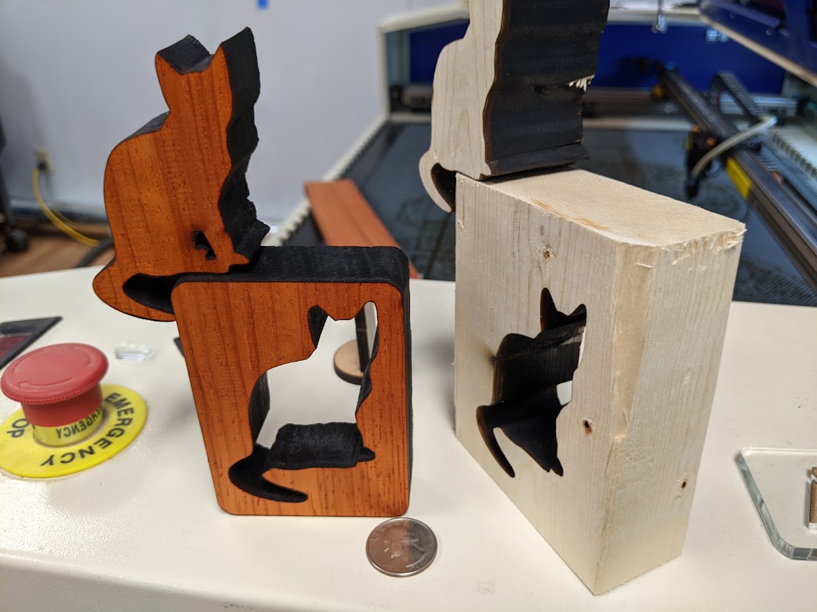
Tarkin cuts lumber up to 1.5" thick (actual dimension), very successfully. The edges are very clean and straight
1/2" black acrylic has cut very well. Thicker may be possible.
Prohibited
NO PVC
NO PVC or ANY FORM OF "VINYL", INCLUDING TRADITIONAL VINYL RECORDS. This is 60% chlorine atoms by weight, and the fumes are corrosive to the equipment. Do not attempt!
NO PTFE (Teflon)
Produces toxic and corrosive gases
NO Polycarbonate
NO POLYCARBONATE ("LEXAN"). This includes CDs, DVDs, and BluRay disks. Although it looks very much like acrylic, polycarbonate does not cut. It turns brown and cracks and produces a ton of soot chains that dirty the optics and whole machine in seconds.
NO METAL
Currently, NO METAL. This included removing paint, aluminum anodization, or fusing Cermark/moly dry lube to steel, aluminum, brass, and copper. While we can normally mark (not cut) metal with a a beam of this power, the reflections may be capable of damaging the laser. If you have such a project, please contact workshop and we can supervise and see how this works.
NO FOOD
The laser cutter is full of unknown toxic chemicals from other materials that may contaminate the food, and food may leave residue that contaminates the machine. It typically smells awful too.
Copper Wire Flame Test
When in doubt, there is a copper wire "flame test" specifically for the presence of toxic/corrosive chlorine as found in PVC:
https://www.youtube.com/results?search_query=laser+cutter+flame+test
Machine Errors
FILE TRANSFER FAILED (seen on the PC)
Causes:
The machine is currently running a job, in a pause or prior halt-for-error- anything that leaves the red light on. If so, press STOP or ESC Ruida panel button to cancel.
The panel was navigated to a menu screen that cannot accept jobs, or the machine is still powered off.
However, about 2% of the time the jobs do get this error from an ethernet prob, but the job simply needs to be re-sent.
WATER PROT
coolant flow not detected. Most likely, the chiller is not turned on.
SYS ALARM, MACHINE PROTECTED
Likely causes:
- Door is open - just close the door
- Chiller is in Alarm state (not turned on, temp out of range, chiller detects no-flow).
- Head crash or excess raster speed has tripped a fault in the drive. Ensure the head is unobstructed and cycle main power
FRAME SLOP
The job sent, with the current user origin, would go outside the bounds of the machine bed. Move the user origin.
NOT ENOUGH EXTEND SPACE
The raster's extend space will go outside the bounds of the machine bed, even if the raster art does not. Move the raster or reduce the rastering speed.
Current Quirks
Table shifting when moving Z
X and Y can shift slightly when Z is moved. Be sure to move the Z before placing the origin. There is a new Z axis kit in-hand to install to fix this.
Fixed air assist
Air assist is a strong flow and has no adjustment yet, and cannot be turned off completely as that would allow smoke in and quickly overheat the lens. The airflow may present a problem for cutting light things like paper, especially thin pieces. Small pieces of thin. light material (including plywood) can also be moved. Inside Lightburn, be sure to select "Cut Inner Shapes First", and manage the cut order in Layers so a piece is not cut free and then something else lasered inside it after it might have shifted in the air flow.
Expected resolution
A mechanical valve is on order that will be added to dial in the flow. It will always allow some air to flow even when closed so there is some flow to protect the lens. In general this should be left full-on.
Drive Faulting
If the motor drive capabilities are exceeded and a drive fault occurs. the machine will stop immediately, and throw a generic "System Protected" error, the same as if the lid is open. This error might occur if we crashing the head into the material, clamp, or jig. One notable symptom, the faulted axis cannot be jogged with the control panel, even though the panel coordinates increment. The other axis moves normally. This fault is resolved by cycling Main Power on Tarkin and letting it rehome. If this fault occurs due to rastering or any case other than crashing the head, please contact workshop with details about settings and, if possible, a copy of the Lightburn project with the settings that led to the fault.
Cone clipping
If the machine is not cutting as fast as usual, please check the temperature of the air assist cone immediately after cutting. Be careful, it can be hot. It is normal to be warm, however, if uncomfortably hot to the touch, the final mirror may need realignment. Please contact workshop immediately, as operation while badly misaligned may damage the lens. This has not been a problem yet.
Maintenance
This tool is owned by Danny Miller and hosted at Asmbly for members to use. Please submit a problem report if maintenance is required.
