Difference between revisions of "Soldering Overhaul"
(Added the Tormach PCNC 1100 equipment page for reference. Drafted a Use Case for the Solder station.) |
(→Setup: Drafted a setup section for the soldering iron.) |
||
| (3 intermediate revisions by the same user not shown) | |||
| Line 1: | Line 1: | ||
| − | The | + | The Electronics lab has an assortment of soldering and de-soldering equipment. |
| − | {{ToolPhoto| | + | {{ToolPhoto|TMT9000s.jpg}} |
| − | |||
| − | |||
*1.5hp R8 Spindle | *1.5hp R8 Spindle | ||
| Line 18: | Line 16: | ||
{{UniversalSafety}} | {{UniversalSafety}} | ||
| − | ====Equipment-Specific Safety==== | + | ==== Equipment-Specific Safety ==== |
| − | + | Safety glasses must be worn when working with the soldering station, as solder can "spit." Never touch the tip of the soldering iron to avoid burns, and always work with the soldering iron above the workbench. When not in use, the soldering iron must be returned to its stand and never laid on its side. The fume extractor should be powered on while soldering to mitigate health risks from inhaling fumes, and skin contact with melted solder should be avoided. | |
| − | + | The soldering iron should only be used for fusing solder, not for other purposes such as burning through materials. Avoid using the soldering iron on the plastic insulation of wires; instead, use a wire stripper to remove the insulation. Additionally, avoid prolonged contact between the soldering iron and PCB boards, as the iron should primarily make contact with the solder. | |
| − | + | Prongs or tweezers are recommended for holding wires while soldering, minimizing the risk of accidental contact with the soldering iron and reducing the chance of burns from conductive heat in the wire. Finally, when finished using the soldering iron, always clean the tip before returning it to its station. | |
| − | |||
| − | |||
| − | |||
==Use Case== | ==Use Case== | ||
| Line 33: | Line 28: | ||
==Materials== | ==Materials== | ||
| + | The soldering station can accommodate two common types of solder wire. | ||
| − | ==== | + | ===== Tin-Lead Rosin Core Solder Wire ===== |
| − | + | Typically has a low melting point, with excellent flow, wetting, and electrical conductivity. Contains lead, which poses health risks through the release of toxic fumes. | |
| − | |||
| − | |||
| − | |||
| − | |||
| − | |||
| − | |||
| − | |||
| − | |||
| − | |||
| − | ==== | + | ===== Lead-Free Rosin Core Solder Wire ===== |
| − | + | Typically has a higher melting point, with good flow, wetting, and electrical conductivity. Produces less harmful fumes, making it safer to work with. | |
| − | |||
==Setup== | ==Setup== | ||
| − | ==== | + | =====Preparing the Soldering Iron===== |
| − | + | *Turn the the power supply unit for the soldering iron. | |
| − | + | **Adjust the temperature of the soldering iron as needed. 400°C typically works for most applications. | |
| − | + | *Wait for about 2 minutes for the soldering iron to heat up. | |
| − | + | *Pick up the soldering iron, burn some solder on the tip of the iron, and clean the tip with copper wool. | |
| − | + | **Doing this before soldering helps improve heat transfer, prevent oxidation, and enhance soldering quality. | |
| − | |||
| − | |||
| − | |||
| − | * | ||
| − | |||
| − | |||
| − | |||
| − | |||
| − | |||
| − | |||
| − | |||
| − | |||
| − | |||
| − | |||
| − | |||
| − | |||
| − | |||
| − | |||
| − | ** | ||
| − | |||
| − | |||
| − | |||
| − | |||
| − | |||
| − | |||
| − | |||
| − | |||
| − | |||
| − | |||
| − | |||
| − | |||
| − | |||
| − | |||
| − | |||
| − | |||
| − | |||
| − | |||
| − | |||
| − | |||
| − | |||
| − | |||
| − | |||
| − | |||
| − | |||
| − | |||
| − | |||
| − | |||
| − | |||
| − | |||
| − | * | ||
| − | |||
| − | |||
| − | |||
| − | |||
| − | |||
| − | |||
| − | |||
| − | * | ||
| − | |||
| − | |||
| − | |||
| − | |||
| − | ** | ||
| − | |||
| − | |||
| − | |||
| − | |||
| − | |||
| − | |||
| − | |||
| − | |||
| − | |||
| − | |||
| − | |||
| − | + | =====Soldering===== | |
| − | * | + | *Use clamps to hold your board in place. |
| − | * | + | *Place the solder wire on the surface you wish to fuse with your wire, then position the soldering iron on top of the solder wire without letting the iron touching the surface. Hold it in place until the solder melts. |
| − | * | + | **A good solder joint should have a smooth, shiny appearance, indicating proper melting and wetting of the solder. It should also be evenly distributed around the connection and have no cracks or excessive lumps. |
| + | *Move the solder wire away, and hold your conductive wire on the melted solder. | ||
| + | **If the wire is insulated, use wire strippers to remove the insulation. | ||
| + | *Move the soldering iron away from the solder, allowing it to harden so that the wire remains adhered to the surface. | ||
| + | *Use the copper wool to clean the soldering iron after every solder. | ||
| − | ===== | + | ===== Cleaning Up Solder ===== |
| + | To clean up solder on a wire or surface, heat the solder with the soldering iron, then place a solder wick near the iron and solder to absorb the solder. You can also use a solder sucker to vacuum the melted solder. | ||
| − | + | ===== Turning Off the Soldering Iron ===== | |
| − | + | When finished using the soldering iron, always ensure to clean the iron tip before storing it back to its holder. '''Turn off the heat when it is not used.''' | |
| − | |||
| − | |||
| − | |||
| − | |||
| − | |||
==Cleanup== | ==Cleanup== | ||
| Line 165: | Line 77: | ||
==Resources== | ==Resources== | ||
| − | |||
| − | |||
| − | |||
| − | |||
| − | |||
| − | |||
| − | |||
====Tooling==== | ====Tooling==== | ||
| Line 181: | Line 86: | ||
====Manual==== | ====Manual==== | ||
| − | *[https:// | + | *[https://hakkousa.com/amfile/file/download/file/19/product/9915/ FX-888 Soldering Station Manual] |
| − | |||
| − | |||
====Discourse Links==== | ====Discourse Links==== | ||
| − | [https://yo.asmbly.org/c/spaces/ | + | [https://yo.asmbly.org/c/spaces/electronics/14 Electronics Shop Space Team] |
====SIG Information==== | ====SIG Information==== | ||
====Speeds and Feeds Resources==== | ====Speeds and Feeds Resources==== | ||
| − | |||
| − | |||
| − | |||
| − | |||
==Troubleshooting== | ==Troubleshooting== | ||
Latest revision as of 01:15, 2 October 2024
The Electronics lab has an assortment of soldering and de-soldering equipment.

- 1.5hp R8 Spindle
- Table Size: 34" x 9.5"
- Table Slots: 3 Slots 5/8"
- Travel: 18" x 9.5" x 16.25" (X,Y,Z)
- Spindle Nose to Table: 17" maximum
- Spindle Center to Column: 11"
- Spindle Nose Diameter: 3 3/8"
- Max Workpiece : 500 lbs Maximum
Safety
Universal Safety
- Be aware of your surroundings, especially when handling large materials.
- Do not approach anyone operating equipment. Stand patiently in their field of view.
Equipment-Specific Safety
Safety glasses must be worn when working with the soldering station, as solder can "spit." Never touch the tip of the soldering iron to avoid burns, and always work with the soldering iron above the workbench. When not in use, the soldering iron must be returned to its stand and never laid on its side. The fume extractor should be powered on while soldering to mitigate health risks from inhaling fumes, and skin contact with melted solder should be avoided.
The soldering iron should only be used for fusing solder, not for other purposes such as burning through materials. Avoid using the soldering iron on the plastic insulation of wires; instead, use a wire stripper to remove the insulation. Additionally, avoid prolonged contact between the soldering iron and PCB boards, as the iron should primarily make contact with the solder.
Prongs or tweezers are recommended for holding wires while soldering, minimizing the risk of accidental contact with the soldering iron and reducing the chance of burns from conductive heat in the wire. Finally, when finished using the soldering iron, always clean the tip before returning it to its station.
Use Case
Soldering uses a fusible metal alloy (solder) to join two metal surfaces by heating them and applying melted solder. It creates electrical connections on PCBs, allowing current to flow between the soldered components.
Materials
The soldering station can accommodate two common types of solder wire.
Tin-Lead Rosin Core Solder Wire
Typically has a low melting point, with excellent flow, wetting, and electrical conductivity. Contains lead, which poses health risks through the release of toxic fumes.
Lead-Free Rosin Core Solder Wire
Typically has a higher melting point, with good flow, wetting, and electrical conductivity. Produces less harmful fumes, making it safer to work with.
Setup
Preparing the Soldering Iron
- Turn the the power supply unit for the soldering iron.
- Adjust the temperature of the soldering iron as needed. 400°C typically works for most applications.
- Wait for about 2 minutes for the soldering iron to heat up.
- Pick up the soldering iron, burn some solder on the tip of the iron, and clean the tip with copper wool.
- Doing this before soldering helps improve heat transfer, prevent oxidation, and enhance soldering quality.
Soldering
- Use clamps to hold your board in place.
- Place the solder wire on the surface you wish to fuse with your wire, then position the soldering iron on top of the solder wire without letting the iron touching the surface. Hold it in place until the solder melts.
- A good solder joint should have a smooth, shiny appearance, indicating proper melting and wetting of the solder. It should also be evenly distributed around the connection and have no cracks or excessive lumps.
- Move the solder wire away, and hold your conductive wire on the melted solder.
- If the wire is insulated, use wire strippers to remove the insulation.
- Move the soldering iron away from the solder, allowing it to harden so that the wire remains adhered to the surface.
- Use the copper wool to clean the soldering iron after every solder.
Cleaning Up Solder
To clean up solder on a wire or surface, heat the solder with the soldering iron, then place a solder wick near the iron and solder to absorb the solder. You can also use a solder sucker to vacuum the melted solder.
Turning Off the Soldering Iron
When finished using the soldering iron, always ensure to clean the iron tip before storing it back to its holder. Turn off the heat when it is not used.
Cleanup
Universal Cleaning Guide
- Return the equipment to neutral.
- Sweep up any dust and debris around the tool, your table top, and the floor - both in the equipment area and your work area.
- Clear the floor of any tripping hazards, like power cords.
- Empty trash cans and dust collectors that are halfway full or more into the Asmbly dumpster behind the workshop.
- Leave the shop 110% better than you found it.
Tool Specific Cleaning Guide
- Hit the E-stop button on the outside of the enclosure
- Clean the whole interior of the enclosure
- Use the appropriate shopvac for the material you machined
- There is a squeegee on the left side of the machine. Use it to remove coolant and chips from the walls of the enclosure. Squeegee the table/fixture plate as well
- Don't forget to move the table of the machine to clean the accordion ways covers on both sides.
- Turn the rotary power switch off
- Return the console to beside the enclosure, out of the aisle
- Make sure the floor in front of the machine is clean and dry
- Return all tools to their proper places
- Return all tool holders to the drawer
Resources
Tooling
- Asmbly has a Tormach SuperFly cutter with inserts for aluminum. These inserts should not be used to cut steel
- There may be a limited selection of end mills and chamfering tools in the drawer with the tool holders
- Tooling used with the manual mills (in the cabinet across from the Rong Fu RF-45 Mill) can be used with the Tormach, but is not high quality and is considered a consumable (will not be replaced if worn or broken)
- It is recommended that you bring in the tooling that you need for your own jobs
Manual
Discourse Links
SIG Information
Speeds and Feeds Resources
Troubleshooting
- Look at the tool paths on the display. Do they look correct? Does the position of the tool onscreen match the physical position of the tool? Make sure the right tool number is selected before comparing. Use the arrow keys to reposition the tool. Are the coordinates what you expect?
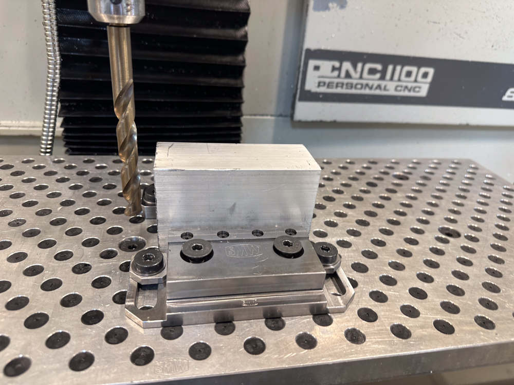
A drill next to some stock to be machined
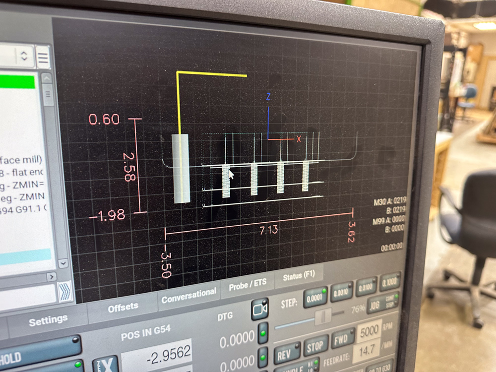
The console showing the drill in the same position relative to the planned path


- Consider stepping through your G-code without a tool in the spindle. Does it move as you expect?
- Click the Single Block button and observe the green indicator
- Click the Cycle Start button to execute one line of G-code
- Are you using the right units? G20 selects inches, G21 selects mm
When in doubt, contact a steward or fill out a problem report