Difference between revisions of "Tormach PCNC 1100"
(→Work Holding: Add dimension info) |
Atwatsoniii (talk | contribs) m (Added more speed and feed resources) |
||
| (5 intermediate revisions by one other user not shown) | |||
| Line 24: | Line 24: | ||
No special PPE is required to use this tool, but hearing protection is advised in addition to the general shop requirements of safety glasses and closed-toed shoes. Safety glasses may be found on a shelf on the back side of the Tormach enclosure, near the [[Central_Machinery_Horizontal_Bandsaw|horizontal bandsaw]]. | No special PPE is required to use this tool, but hearing protection is advised in addition to the general shop requirements of safety glasses and closed-toed shoes. Safety glasses may be found on a shelf on the back side of the Tormach enclosure, near the [[Central_Machinery_Horizontal_Bandsaw|horizontal bandsaw]]. | ||
| + | |||
| + | This machine rotates the spindle very rapidly. Don't wear loose clothing when operating this machine. It may be hard to see exactly where rapidly spinning tools are, particularly fly cutters. | ||
| + | |||
| + | Do not reach into the enclosure while the machine is moving. The space bar triggers FEEDHOLD, which stops feeding, but '''does not stop the spindle'''. Stop the spindle as well as stopping feeding (bed movement) by sliding the RPM slider to 0% on the console. The STOP button will reset your program to the beginning. | ||
| + | |||
| + | Keep the enclosure doors closed as much as possible. Objects may be sent flying in any direction, including detached pieces, or the entire part being machined if work holding fails. | ||
==Use Case== | ==Use Case== | ||
| − | The Tormach is used for [[wikipedia:Numerical_control|CNC machining]]. It can be | + | The Tormach is used for [[wikipedia:Numerical_control|CNC machining]]. It can be used to create precise parts out of a variety of materials, including metals, plastics, and wood. |
| − | used to create precise parts out of a variety of materials, including metals, plastics, and wood. | ||
==Materials== | ==Materials== | ||
| Line 60: | Line 65: | ||
File:Tormach Oiler.jpg|Oil reservoir level | File:Tormach Oiler.jpg|Oil reservoir level | ||
</gallery> | </gallery> | ||
| − | *Check the coolant pressure. Open the valve fully and click the COOLANT button on the console. The stream should have enough pressure to remain straight over several inches. If you need to add coolant, mix 5-10% concentrate and the rest distilled water. The concentrate is a brown liquid that should be in the tall cabinet in the machining area. Give it a good shake to mix it before adding it to the reservoir. You can pour the coolant into the drain in the enclosure. Pay attention to the coolant pressure as you operate the tool. If it gets low, pause your job and add more coolant. <gallery> | + | *Turn on the rotary power switch, found on the right side of the machine, inside the enclosure |
| + | * When the console comes on, click on Mill to enter the control interface | ||
| + | * Check the coolant pressure. Open the valve fully and click the COOLANT button on the console. The stream should have enough pressure to remain straight over several inches. If you need to add coolant, mix 5-10% concentrate and the rest distilled water. The concentrate is a brown liquid that should be in the tall cabinet in the machining area. Give it a good shake to mix it before adding it to the reservoir. You can pour the coolant into the drain in the enclosure. Pay attention to the coolant pressure as you operate the tool. If it gets low, pause your job and add more coolant.<gallery> | ||
File:Tormach Coolant Flow Good.jpg|Good coolant flow | File:Tormach Coolant Flow Good.jpg|Good coolant flow | ||
File:Tormach Low Coolant Pressure.jpg|Insufficient flow | File:Tormach Low Coolant Pressure.jpg|Insufficient flow | ||
| Line 66: | Line 73: | ||
File:Mixing the coolant.jpg|Mixing the coolant | File:Mixing the coolant.jpg|Mixing the coolant | ||
</gallery> | </gallery> | ||
| − | |||
| − | |||
=====Transferring Files===== | =====Transferring Files===== | ||
| Line 110: | Line 115: | ||
*[https://saundersmachineworks.com/products/tormach_1100_aluminum_fixture_plate Saunders Machine Works fixture plate] | *[https://saundersmachineworks.com/products/tormach_1100_aluminum_fixture_plate Saunders Machine Works fixture plate] | ||
**The fixture plate allows for precision, repeatable placement of vises and fixtures, greatly improving the speed of making multiple parts. | **The fixture plate allows for precision, repeatable placement of vises and fixtures, greatly improving the speed of making multiple parts. | ||
| + | **'''The fixture plate is 34" x 12". The Tormach travel is only 18" x 9.5". This means that much of the fixture plate can't be reached by the spindle, so before fixturing a part to the table, make sure it will be accessible.''' | ||
**The fixture plate is trammed to the mill table movement. Do not loosen or remove the low-profile screws in the fixture plate that secure it to the mill table, it is quite difficult to re-tram and in almost all cases, unnecessary to remove. | **The fixture plate is trammed to the mill table movement. Do not loosen or remove the low-profile screws in the fixture plate that secure it to the mill table, it is quite difficult to re-tram and in almost all cases, unnecessary to remove. | ||
**The holes are spaced 1.25" on-center | **The holes are spaced 1.25" on-center | ||
| Line 187: | Line 193: | ||
====SIG Information==== | ====SIG Information==== | ||
| − | ==== | + | ====Speeds and Feeds Resources==== |
| − | *[https://provencut.com/ ProvenCut] | + | *[https://provencut.com/ ProvenCut] |
| + | *[https://fswizard.com/ FSWizard Machinist Calculator] | ||
| + | *[https://nyccnc.com/speeds-feeds-excel-worksheet/ NYCNC Speeds and Feeds Excel Worksheet] | ||
==Troubleshooting== | ==Troubleshooting== | ||
Latest revision as of 02:26, 20 September 2024
 Members must complete the Tormach Class before using this tool
The Tormach PCNC 1100 is in an enclosure on the edge of the metal shop, adjoining the wood shop.

- 1.5hp R8 Spindle
- Table Size: 34" x 9.5"
- Table Slots: 3 Slots 5/8"
- Travel: 18" x 9.5" x 16.25" (X,Y,Z)
- Spindle Nose to Table: 17" maximum
- Spindle Center to Column: 11"
- Spindle Nose Diameter: 3 3/8"
- Max Workpiece : 500 lbs Maximum
Safety
Universal Safety
- Be aware of your surroundings, especially when handling large materials.
- Do not approach anyone operating equipment. Stand patiently in their field of view.
- Use PPE, including filtration and eye protection, when handling dust or emptying dust/shaving containers.
Equipment-Specific Safety
Tormach Class is required to use this tool.
No special PPE is required to use this tool, but hearing protection is advised in addition to the general shop requirements of safety glasses and closed-toed shoes. Safety glasses may be found on a shelf on the back side of the Tormach enclosure, near the horizontal bandsaw.
This machine rotates the spindle very rapidly. Don't wear loose clothing when operating this machine. It may be hard to see exactly where rapidly spinning tools are, particularly fly cutters.
Do not reach into the enclosure while the machine is moving. The space bar triggers FEEDHOLD, which stops feeding, but does not stop the spindle. Stop the spindle as well as stopping feeding (bed movement) by sliding the RPM slider to 0% on the console. The STOP button will reset your program to the beginning.
Keep the enclosure doors closed as much as possible. Objects may be sent flying in any direction, including detached pieces, or the entire part being machined if work holding fails.
Use Case
The Tormach is used for CNC machining. It can be used to create precise parts out of a variety of materials, including metals, plastics, and wood.
Materials
Acceptable Materials
With the proper tooling, many materials can be machined. Common choices include Aluminum, Steel, and Acetal plastic ("Delrin"). Wood may also be machined on the Tormach.
Maximum Sizes and Weights
- Size: 18" x 9.5" x 16.25" (X,Y,Z)
- Weight: 500 lbs
Consumables
Distilled water can be found underneath the tool. Coolant concentrate can be found in the machine shop tool cabinet under the loft. See Turning on the machine below.
Feeds and Speeds
The Tormach is configured in the High Belt position, which gives a range of 250-5140 RPM at the spindle. ProvenCut is a good source for tested feeds and speeds.
Setup
Controls
There is a rotary power switch inside the enclosure on the right side of the machine. There is a power button and an emergency stop button (E-stop) above the enclosure doors. The console is on a swinging arm on the right side of the enclosure. The jog dial works, but is not great for controlling the machine. The arrow keys and Page Up/Dn move the bed while the machine is idle.
The lights inside the enclosure are controlled by turning on/off the power strip on top.
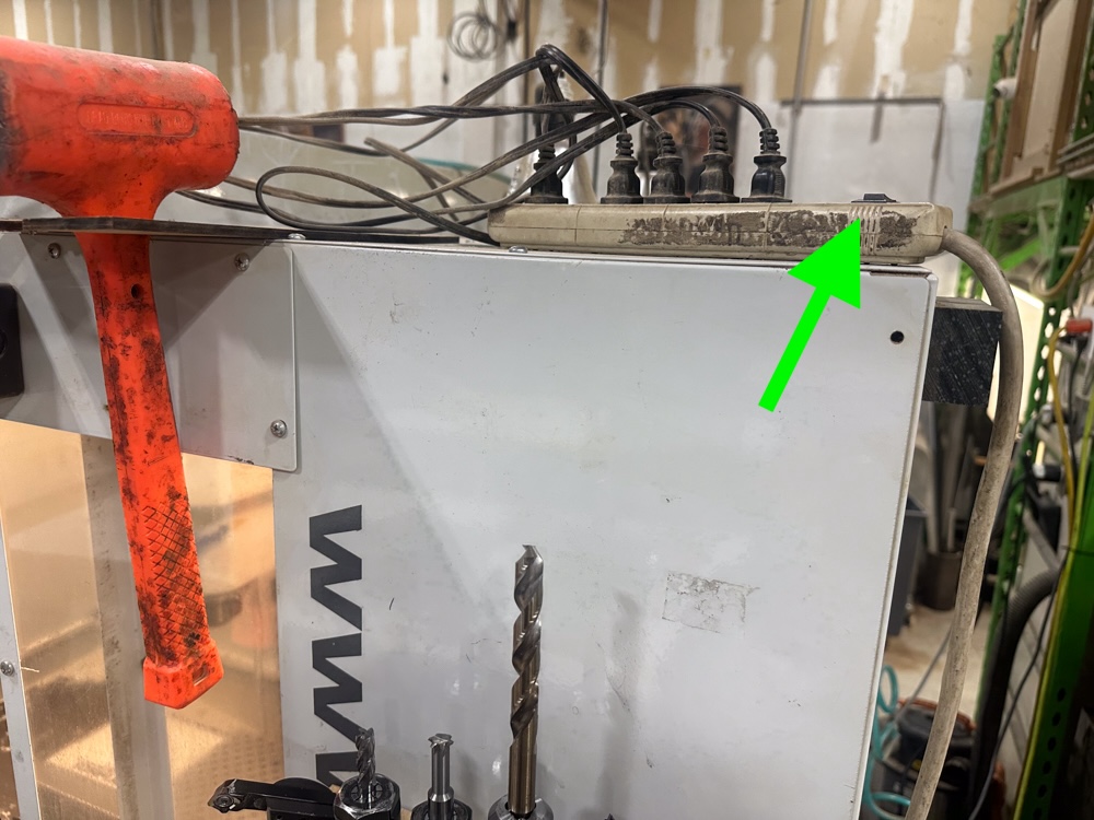
Enclosure lights power switch

Basic Operation
Using this tool requires you to book time in Skedda under "Metal Shop - Tormach".
Turning on the Machine
- Check the oiler, which is on the lower left side of the machine. Contact a steward if the oil level is low
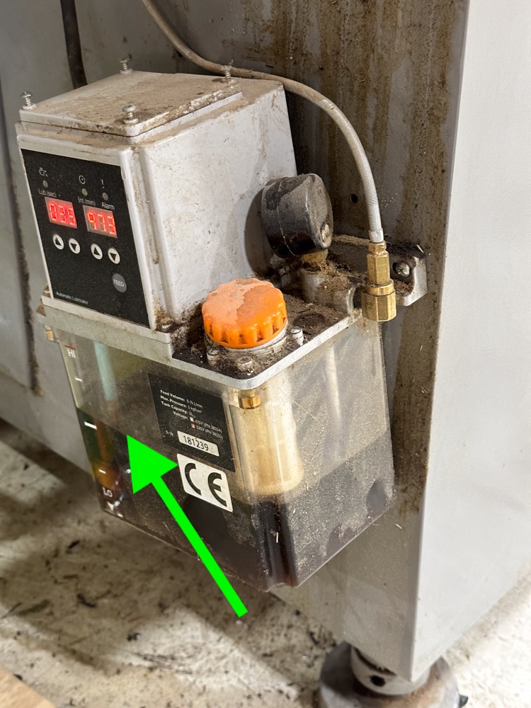
Oil reservoir level

- Turn on the rotary power switch, found on the right side of the machine, inside the enclosure
- When the console comes on, click on Mill to enter the control interface
- Check the coolant pressure. Open the valve fully and click the COOLANT button on the console. The stream should have enough pressure to remain straight over several inches. If you need to add coolant, mix 5-10% concentrate and the rest distilled water. The concentrate is a brown liquid that should be in the tall cabinet in the machining area. Give it a good shake to mix it before adding it to the reservoir. You can pour the coolant into the drain in the enclosure. Pay attention to the coolant pressure as you operate the tool. If it gets low, pause your job and add more coolant.
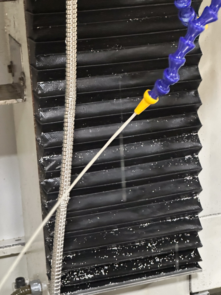
Good coolant flow
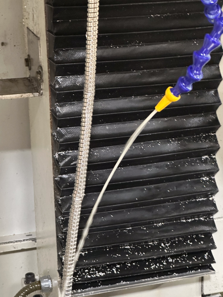
Insufficient flow
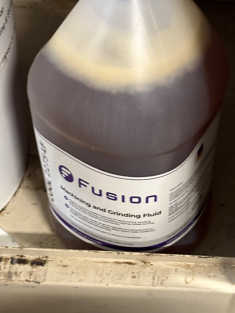
Coolant concentrate
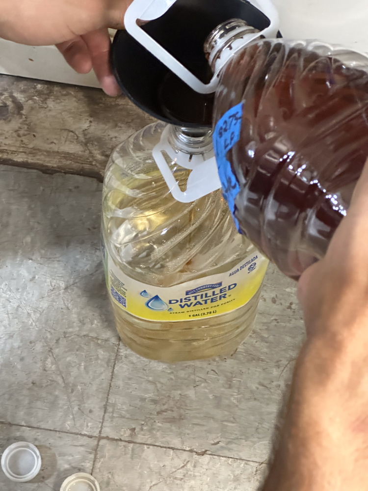
Mixing the coolant


Transferring Files
- There is a USB Hub that can read FAT-formatted USB drives. Use the FILES tab in the console to transfer files to the console
- You can transfer files over the network
- Browse the Asmbly wifi network for
tormachpcncand mount thegcodeshare as a guest, or connect tosmb://tormachpcnc(Mac) or\\tormachpcnc(Windows)
- Browse the Asmbly wifi network for
Preparing Tools
- Tool holders and a limited selection of tools can be found in the black cabinet to the right of the machine.
- For common tool sizes, 1/8", 1/4", 3/8", and 1/2" ER20 collets are available, as are two sizes of drill chuck. See the descriptions here for details.
- To place a tool in an ER20 collet, choose the correct size of collet, place into the collet nut so that the face of the collet is flush with the nut, lightly tighten the nut onto the tool holder, insert the tool, tighten the nut.
- There is a tool tightening fixture mounted on the cabinet top. To tighten, insert the collet in the left side of the bushing and tighten with the wrench. To loosen, insert the collet in the right side of the bushing and loosen with the wrench
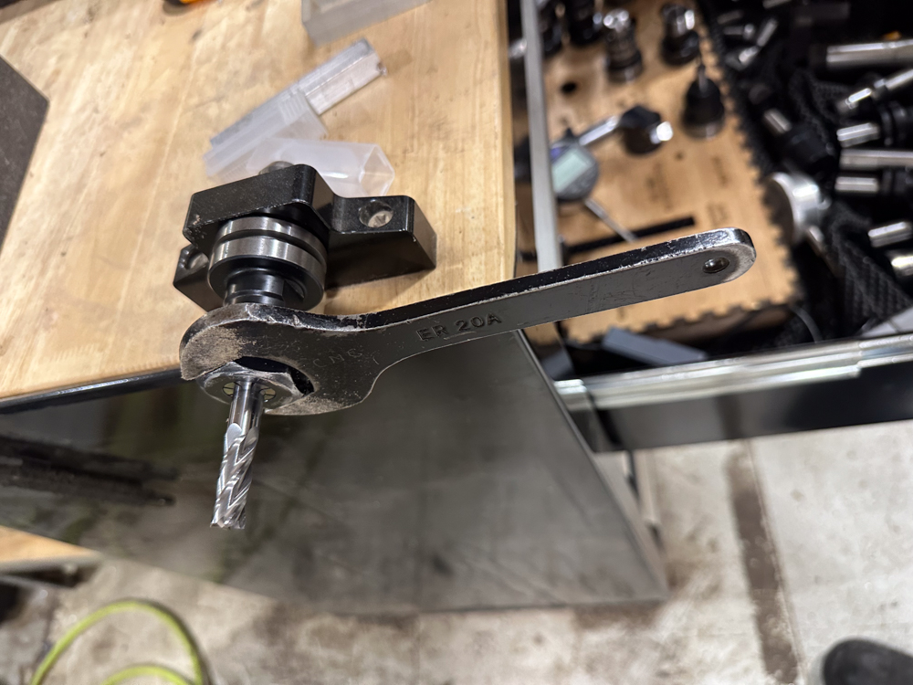
A tool in an ER20 collet on the left side of the fixture with a wrench

- After securing tools in the tool holder, measure their lengths using the surface plate and height gauge
- Place the tool holder in the hole in the surface plate
- Turn on the micrometer, adjust the measuring tip to rest on the surface plate and zero it
- Raise the measuring tip to the top of the tool
- Record the length in the OFFSETS screen of the console with the appropriate tool number
- Place the tool into the laser cut holder
Inserting & Removing Tools
- To insert:
- Open the spindle cover door
- Immobilize the spindle using the locking arm
- Place the tool holder into the collet and hold with your left hand
- Tighten the drawbar using the wrench (kept above and to the left of the enclosure doors)
- Move the locking arm out of the way
- Close and secure the spindle cover door. If it won't close, you may have left the locking arm in place
- To remove:
- Open the spindle cover door
- Immobilize the spindle using the locking arm
- Hold the tool holder with your left hand
- Loosen the drawbar using the wrench
- If the tool holder doesn't come loose, make sure you're holding the tool holder and lightly tap the top of the drawbar with the back of the wrench
- Move the locking arm out of the way
- Close and secure the spindle cover door
Work Holding
- Saunders Machine Works fixture plate
- The fixture plate allows for precision, repeatable placement of vises and fixtures, greatly improving the speed of making multiple parts.
- The fixture plate is 34" x 12". The Tormach travel is only 18" x 9.5". This means that much of the fixture plate can't be reached by the spindle, so before fixturing a part to the table, make sure it will be accessible.
- The fixture plate is trammed to the mill table movement. Do not loosen or remove the low-profile screws in the fixture plate that secure it to the mill table, it is quite difficult to re-tram and in almost all cases, unnecessary to remove.
- The holes are spaced 1.25" on-center
- Each hole in the fixture plate will accept a 1/2" dowel pin for alignment or work stop use, and is also threaded for standard 1/2-13 bolts.
- To preserve the integrity of the threads in all of these holes, each hole is plugged with a black rubber plug when not in use. You should not operate the mill with any exposed holes, they should always have either a plug, a dowel, or a bolt in them. This keeps chips and coolant out and makes cleanup much simpler.
- To remove and replace the plugs, there is hook / pick tool in the tool chest. Pierce the center dot on the plugs with the pick, twist, and pull up. This motion will eventually deteriorate the plugs. If they appear to be in need of replacement, more are available in the tool chest, but simply piercing the center dot doesn't render them inoperable.
- The fixture plate works best with fixtures or mod vises. If you want to use a standard machine vise, it will bolt to the fixture plate using 1/2-13 bolts. The machine vise will need to be trammed with a dial indicator if you install it.
- Because the fixture plate is uncoated aluminum, it is subject to galvanic corrosion if steel or cast iron is left attached to it long term. There are small tubes of dielectric grease available in the tool chest. Ideally a thin coat should be maintained on the vises if they are being left on the plate for an extended period of time. The bottom of the plate has also been coated to prevent corrosion between the plate and the table. One tube of grease is enough to coat the entire surface area of the fixture plate, so use it sparingly.
- 2 Saunders Machine Works Mod Vises
- Diagram with dimensions
- These are the preferred vises to use with the fixture plate. For most use cases, they will provide a superior user experience to a traditional machine vise.
- These are also precision ground instruments. Every surface is machined and the fixed-side jaw can be used as a reliable work coordinate system origin.
- Mod vises require no tramming, they can be moved around the plate at will.
- One vise is set up with smooth jaws, the other with talon jaws
- There is a short video tutorial that illustrates proper usage here
Referencing
After turning the machine on, or after an E-stop, the machine must be referenced.
- Click the Reset button (note, this will also reset your G-code to the start)
- Click Ref Z first, to raise the spindle
- Click Ref X and Ref Y
Probing
- The probe is in a labeled hard case in the tool chest. The case contains the probe, cable, and a very easy to miss hex wrench that is used for adjusting concentricity.
- The probe has already been indicated and measured in PathPilot, and should be ready to use.
- The probe's cable has been hot glued to the probe itself. If the cable is not connected to the probe for any reason, please red tag the machine so we can address that issue to prevent crashing and ruining the probe. To start, ALWAYS plug the into the DIN5 cable into the accessory port on the machine electronics cabinet FIRST. The probe will light up green when the connection is good. DO NOT proceed if the light is not on. The machine will happily crash and ruin the probe if you run a probing routine without power to the probe.
- Next, put the probe in the collet and tighten the collet. Light / hand-tight is sufficient. It's a good practice to leave the spindle cover door open while the probe is in the collet, this guarantees you'll never spin up the machine with the probe in the collet.
- Once the cable is connected and the probe is installed, select tool 99 in the tool DRO. The probe is hard coded in PathPilot to be tool 99.
- Tormach has a good video overview of how to use the various probing routines here
- Put the probe back in the tool chest when you're done
Cleanup
Universal Cleaning Guide
- Return the equipment to neutral.
- Sweep up any dust and debris around the tool, your table top, and the floor - both in the equipment area and your work area.
- Clear the floor of any tripping hazards, like power cords.
- Empty trash cans and dust collectors that are halfway full or more into the Asmbly dumpster behind the workshop.
- Leave the shop 110% better than you found it.
Tool Specific Cleaning Guide
- Hit the E-stop button on the outside of the enclosure
- Clean the whole interior of the enclosure
- Use the appropriate shopvac for the material you machined
- There is a squeegee on the left side of the machine. Use it to remove coolant and chips from the walls of the enclosure. Squeegee the table/fixture plate as well
- Don't forget to move the table of the machine to clean the accordion ways covers on both sides.
- Turn the rotary power switch off
- Return the console to beside the enclosure, out of the aisle
- Make sure the floor in front of the machine is clean and dry
- Return all tools to their proper places
- Return all tool holders to the drawer
Resources
Software
While any CAD software may be used to design your parts, Autodesk Fusion (fka Fusion 360) is recommended to generate your tool paths.
Fusion is installed on the computers in the Textiles room. Autodesk offers free subscriptions for educational users. Autodesk also offers a personal subscription for non-commercial use, however be aware that the personal version doesn't support post processing NC paths with tool changes. Transferring projects from a personal account to another account is surprisingly difficult.
Tooling
- Asmbly has a Tormach SuperFly cutter with inserts for aluminum. These inserts should not be used to cut steel
- There may be a limited selection of end mills and chamfering tools in the drawer with the tool holders
- Tooling used with the manual mills (in the cabinet across from the Rong Fu RF-45 Mill) can be used with the Tormach, but is not high quality and is considered a consumable (will not be replaced if worn or broken)
- It is recommended that you bring in the tooling that you need for your own jobs
Manual
Discourse Links
SIG Information
Speeds and Feeds Resources
Troubleshooting
- Look at the tool paths on the display. Do they look correct? Does the position of the tool onscreen match the physical position of the tool? Make sure the right tool number is selected before comparing. Use the arrow keys to reposition the tool. Are the coordinates what you expect?
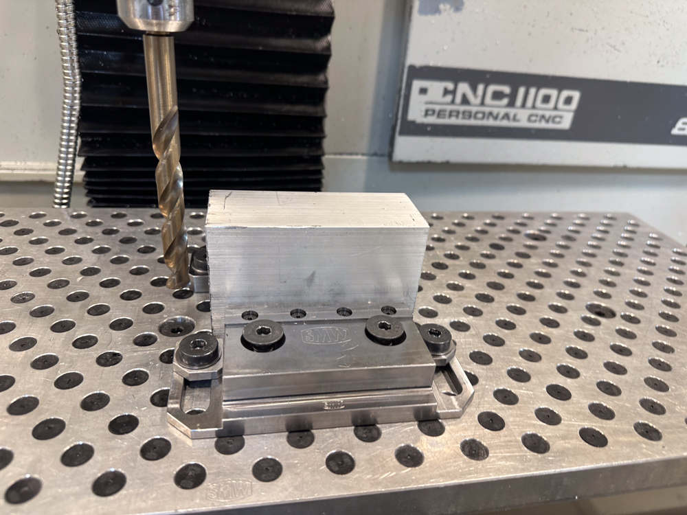
A drill next to some stock to be machined
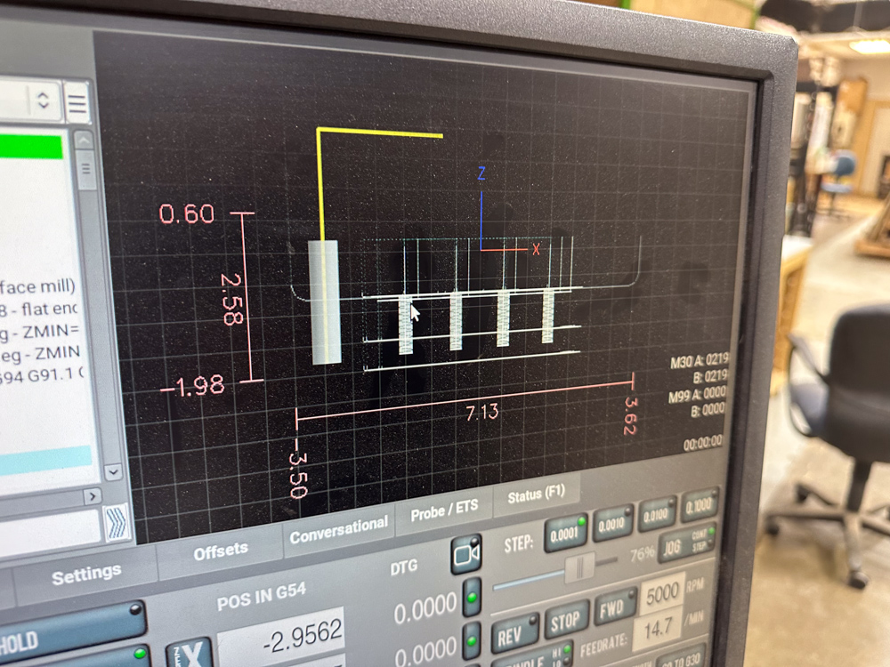
The console showing the drill in the same position relative to the planned path


- Consider stepping through your G-code without a tool in the spindle. Does it move as you expect?
- Click the Single Block button and observe the green indicator
- Click the Cycle Start button to execute one line of G-code
- Are you using the right units? G20 selects inches, G21 selects mm
When in doubt, contact a steward or fill out a problem report